Vertebral osteosynthetis equipment

a technology of vertebral osteosynthetis and equipment, which is applied in the direction of osteosynthesis devices, prostheses, surgical staples, etc., can solve the problems of significant drawbacks of being strongly invasive and complicated surgical operations

Active Publication Date: 2015-02-17
MEDICREA INT SA
View PDF63 Cites 62 Cited by
  • Summary
  • Abstract
  • Description
  • Claims
  • Application Information

AI Technical Summary

Benefits of technology

[0016]the assembling member comprises a conduit which allows it to be engaged and closely fitted on this same guiding rod, and connecting means able to cooperate with the connecting means of the proximal portion of the hole of the implant.
[0019]The guiding rod thus allows the assembling member to be perfectly guided and aligned with the axis of the hole of the implant.
[0020]The result is that with the piece of equipment according to the invention, the assembling of the connecting member with the implant may be carried out under the best conditions, and the placement of the assembling member is easy, which allows the use of a narrow and not very invasive approach, in particular a purely side approach.
[0038]With the piece of equipment according to the invention, it is thereby possible to obtain, in addition to perfect coaxiality of the assembling member with the hole of the implant, perfect parallelism of the holes made in the vertebral bodies with this same hole of the implant, and coaxiality of the hole of the connecting member with this hole of the implant.
[0044]This wall creates an area of sufficient thickness for creating this hole and allows longitudinal reinforcement of the implant, making the latter able to support without any risk of deterioration the stresses generated by its introduction and / or its impaction into the intervertebral space.

Problems solved by technology

This anterior approach however has the significant drawback of being strongly invasive and of making the surgical operation complicated.

Method used


Image

  • Vertebral osteosynthetis equipment
  • Vertebral osteosynthetis equipment
  • Vertebral osteosynthetis equipment

Examples


Embodiment Construction

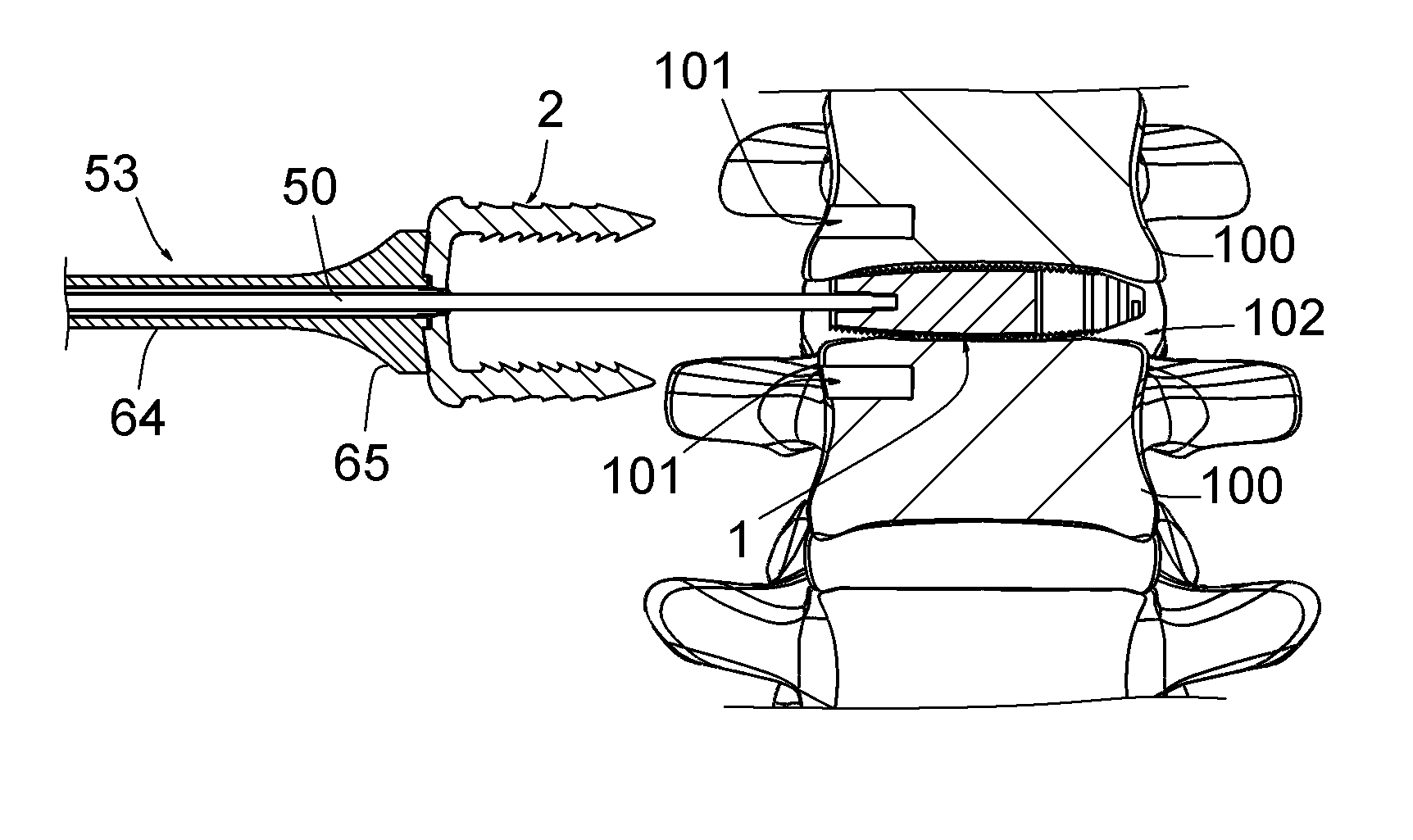
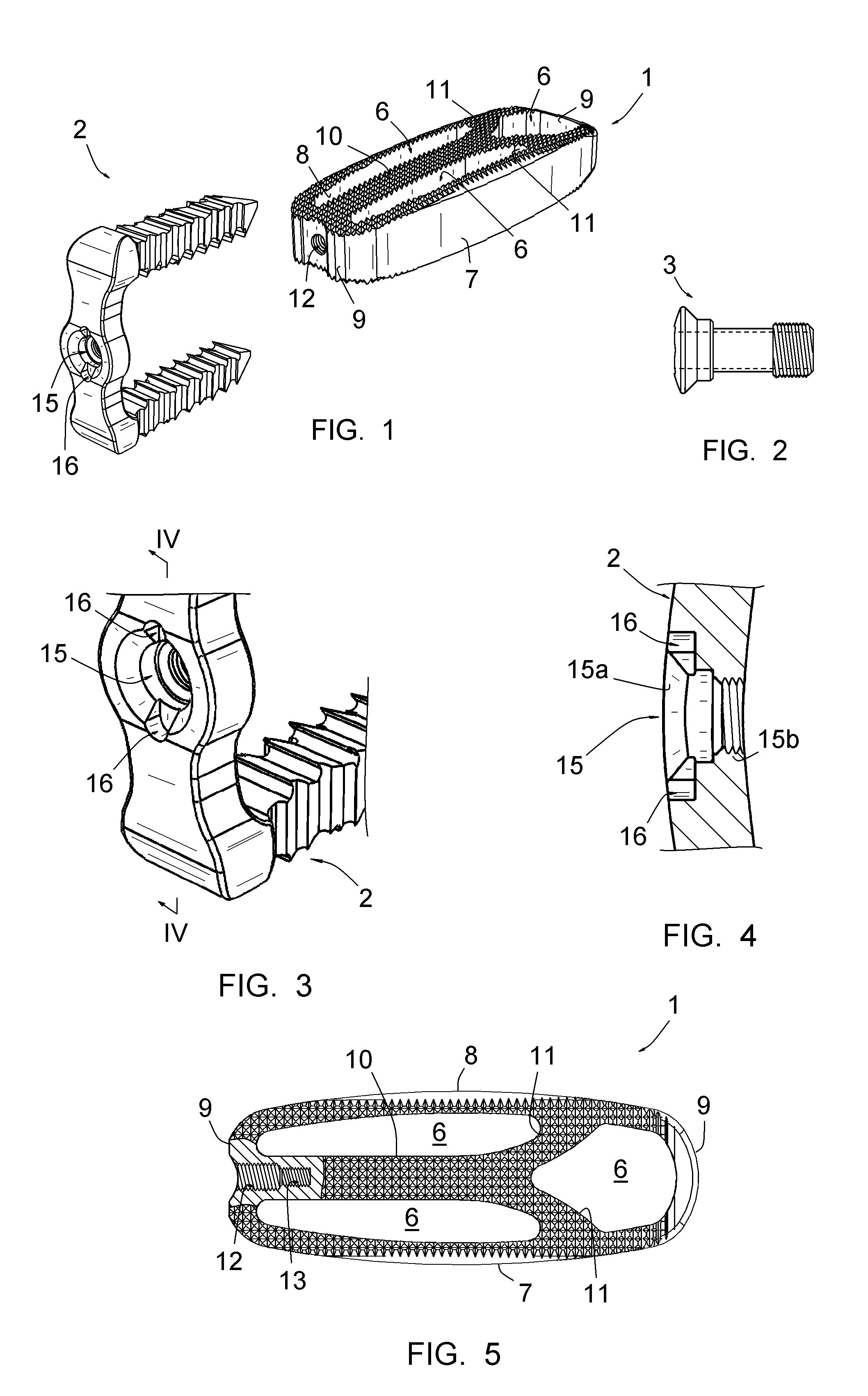
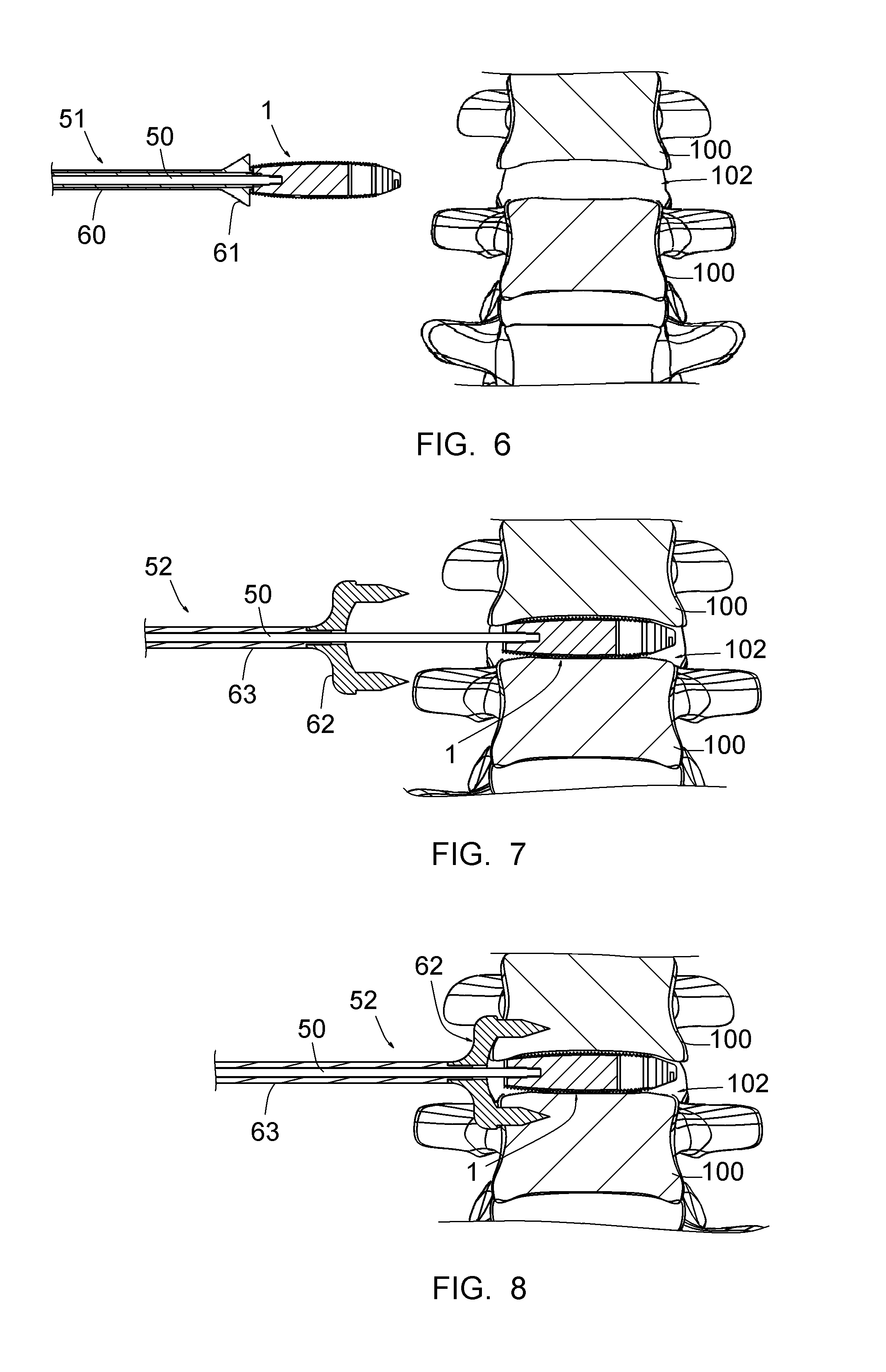
[0062]The FIGS. 1-5 represent a piece of vertebral osteosynthesis equipment including an intervertebral implant 1, a member 2 for connecting the vertebral bodies 100 of two treated vertebrae, an assembling member 3 for assembling the connecting member 2 to the intervertebral implant, and FIGS. 12-16 represent instruments 50-54 for placing this implant 1, this connecting member 2 and this assembling member 3.

[0063]By more particularly referring to FIGS. 1 and 5, it appears that the intervertebral implant 1 is in the form of a cage delimiting cavities 6 for receiving porous, bone or synthetic grafts. These grafts are intended to be colonized by growing bone cells, so as to achieve what should be called “bone fusion” of the vertebrae.

[0064]The implant 1 is intended to be introduced into the intervertebral space to be treated via a side approach. It comprises peripheral walls, including an anterior wall 7, a posterior wall 8 and side walls 9. It also comprises internal walls, including ...


PUM


Abstract

A vertebral osteosynthesis equipemnt including an intervertebral implant (1); a member (2) for connecting vertebral bodies (100) of both treated vertebrae intended to be assembled to the intervertebral implant (1); and a member (3) for assembling the connecting member (2) to the intervertebral implant (1). The intervertebral implant (1) includes on its proximal side relatively to the direction of its introduction into the intervertebral space (102), a hole comprising two coaxial portions, i.e. a proximal portion of larger section and a distal portion of smaller section, these proximal and distal portions comprising respective connecting means. The connecting member (2) includes a hole which allows it to be engaged onto a guiding rod (50) intended to be inserted into said distal portion (13) of the hole of the implant (1), and the assembling member (3) comprises a conduit on this guiding rod (50).

Description

CROSS REFERENCE TO RELATED APPLICATION[0001]This application is a national stage entry of PCT / IB2010 / 051821 filed Apr. 26, 2010, under the International Convention, claiming priority over FR 0902030 filed Apr. 27, 2009.FIELD OF THE INVENTION[0002]The present invention relates to a piece of vertebral osteosynthesis equipment.BACKGROUND TO THE INVENTION[0003]The immobilization of two consecutive vertebrae by placing between these vertebrae, an implant intended to be colonized by growing bone cells so as to achieve what should be called “bone fusion” of the vertebrae, is well known. This intervertebral implant may notably be in the form of a cage in stiff material, against which the vertebrae bear, the cavity(ies) of which receive(s) a porous, bone or synthetic graft.[0004]Associating with the intervertebral implant, a member for connecting two vertebrae externally to the intervertebral space, notably as a clamp, is also known, the respective branches of which are inserted into the bod...

Claims


Application Information

Patent Timeline
Patent Type & Authority Patents(United States)
IPC IPC(8): A61F2/44A61B17/064A61B17/70A61F2/28A61F2/30A61F2/46
CPCA61F2/4455A61F2/4611A61B17/0642A61B17/7059A61F2/447A61F2002/2835A61F2002/30433A61F2002/30507A61F2002/30576A61F2002/30604A61F2002/30892A61F2002/30904A61F2002/4475A61F2002/4627A61F2002/4629A61F2220/0025A61F2220/0041A61F2002/30593
Inventor MCCARTHY, KEVIN
Owner MEDICREA INT SA
Why Eureka
Try Eureka