Device and method for repairing pipe

a technology for repairing devices and pipes, applied in shaft equipment, surface layering apparatus, manufacturing tools, etc., can solve the problems of time wear away, reduced service life, and damage at the junction between the lateral pipe and the main pipe, and achieve good resin migration withou, sufficient wall thickness, and sacrifice the wall thickness of the lining

Active Publication Date: 2009-08-06
LMK TECH LLC
View PDF48 Cites 61 Cited by
  • Summary
  • Abstract
  • Description
  • Claims
  • Application Information

AI Technical Summary

Benefits of technology

[0012]It is therefore a principal object, aspect, feature or advantage of the present invention to provide an apparatus and method for repairing a pipeline which improves over or solves the problems and deficiencies in the art.
[0013]Other objects, features, aspects and / or advantages of the invention relate to an apparatus and method which provides for good resin migration without sacrificing the wall thickness of the lining when high pressures are used to install the lining.
[0014]Further objects, features, aspects and / or advantages of the invention relate to a new liner that is durable and maintains sufficient wall thickness while still effectively repairing the damaged section of pipe.
[0015]Further objects, features, aspects and / or advantages of the invention relate to a new liner having a substantially impervious layer, providing a long service life leak-free lining.
[0016]These and other objects, features, aspects and advantages of the present invention will become more apparent with reference to the accompanying specification and claims.
[0017]The present invention may be used in all types of pipelining, such as lining an entire main sewer pipe from manhole to manhole, lining a section of sewer pipe, lining the entire length of a lateral pipe, lining a potable water main, lining a gas pipeline, lining a lateral pipe and the connection to a main pipe and other pipelines, conduits, ducts, casings, vaults, manholes, and similar structures. However, the advantages of the invention will be most appreciated by those skilled in the art when the invention is used for lining a lateral pipe and its connection to a main pipe.

Problems solved by technology

Often damage occurs at the junction between the lateral pipe and the main pipe.
However, these coatings are made of a thin plastic film, which over time wear away due to abrasion from water flow, silt and cleaning tools.
Service life is reduced when the film coatings are worn away as leakage occurs.
However, when using a one-piece main / lateral bladder assembly, the high pressure required to evert the lateral liner is also the same pressure being applied to the main liner.
When a resin impregnated tube is pressurized and pressed against the interior of the host pipe, resin migrates into open joints and fractures in the pipe.
However, when higher pressures are required to evert the lateral lining tube into the lateral pipeline, this pressure squeezes the flexible tube, causing the main / lateral liner assembly near the juncture between the main and lateral liners to become thin with insufficient wall thickness for the desired design calculations.

Method used


Image

  • Device and method for repairing pipe
  • Device and method for repairing pipe
  • Device and method for repairing pipe

Examples


Embodiment Construction

[0044]For a better understanding of the invention, several examples of forms of the invention will now be described in detail. Frequent reference will be made to the accompanying figures. Reference numerals will be used to indicate certain parts or locations in the figures. The same reference numerals will be used to indicate the same or similar parts or locations throughout the figures unless otherwise indicated.

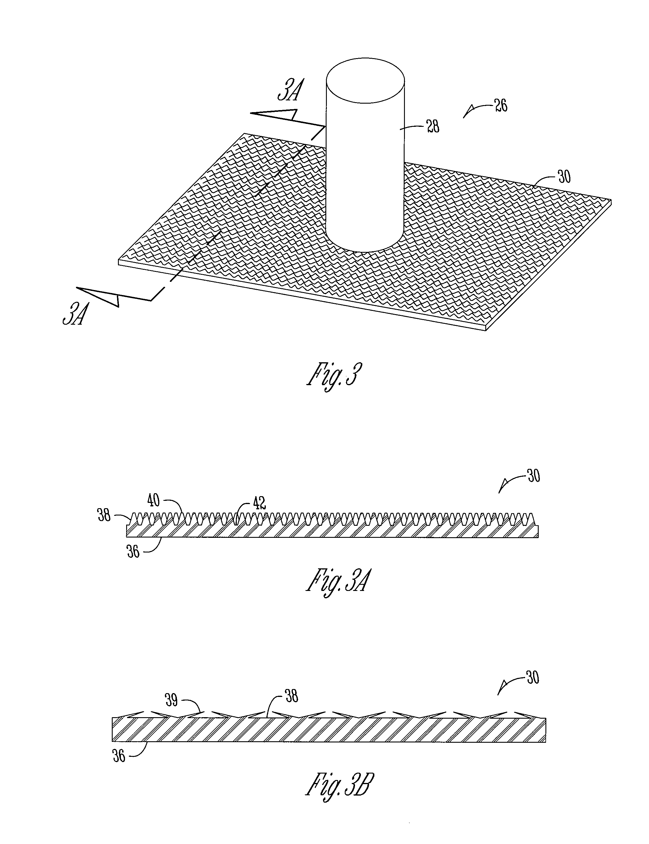
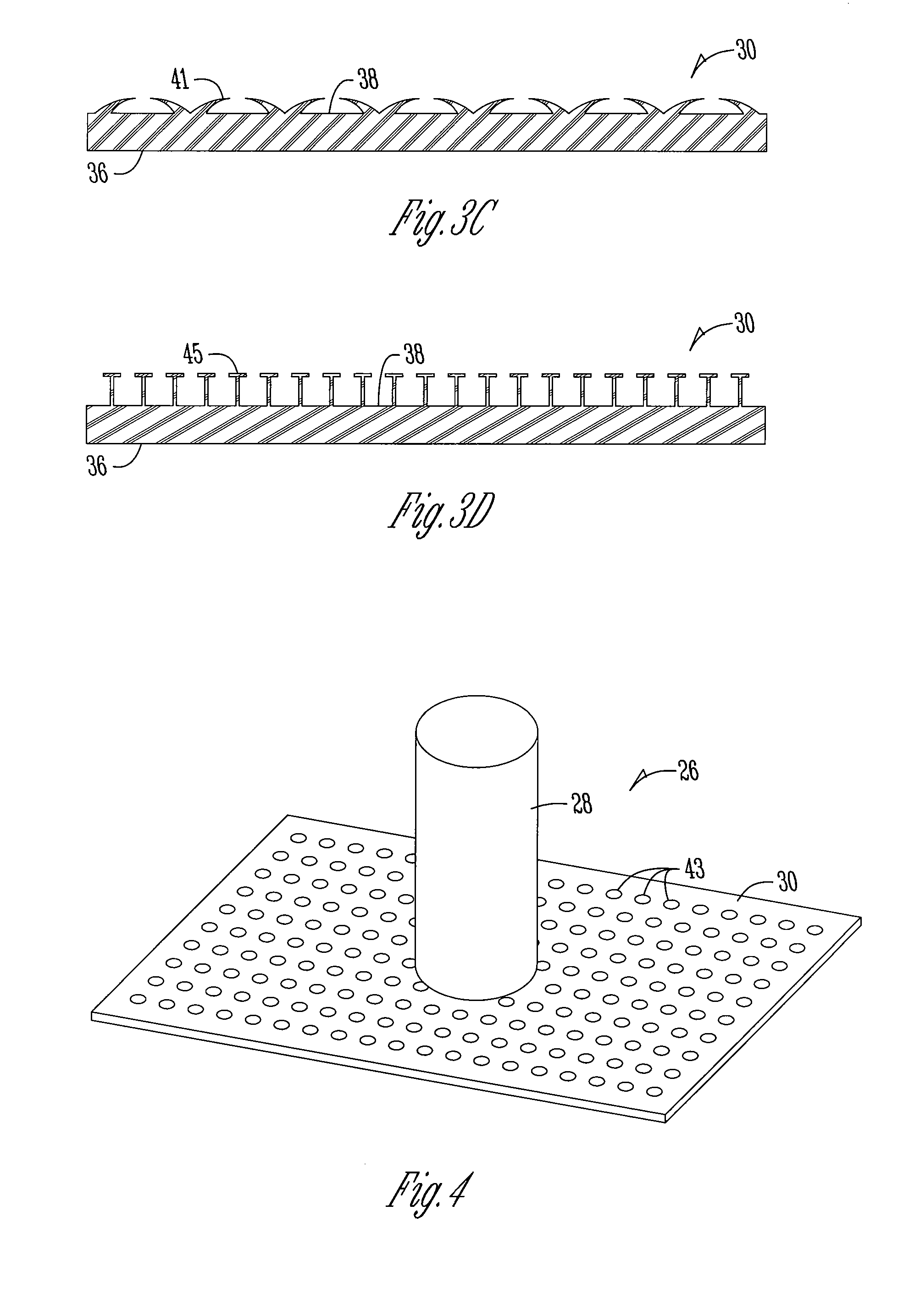
[0045]Referring to FIG. 3, a main / lateral liner assembly is generally designated by the numeral 26. The liner assembly 26 includes a lateral liner tube 28 and a main liner member or portion 30.

[0046]The lateral liner tube 28 is made from a needle punched felt lining material with a plastic film lining on the outside. The coating is made from an impervious thermoplastic film, such as PE, PVC, or PU, as previous discussed. If the lateral liner tube 28 is to be everted into a lateral pipeline, then the plastic film coating is initially on the outside of the tube so that when t...


PUM

PropertyMeasurementUnit
thicknessaaaaaaaaaa
thicknessaaaaaaaaaa
diameteraaaaaaaaaa

Abstract

The present invention relates to a new liner for repairing a damaged portion of a pipe. A lining tube formed from a non-resin absorbent material has an exterior surface adapted to receive a curable resin and contact an interior wall of the pipe. The present invention also includes a main / lateral liner assembly for repairing the junction between main and lateral pipes using a non-resin absorbent liner for at least a portion of the lining.

Description

BACKGROUND OF THE INVENTION[0001]The present invention relates to a device and method for repairing pipe, such as underground sewer pipe and the like.[0002]Prior methods for repairing damaged pipelines include moving a liner tube impregnated with a liquid material capable of curing and hardening to a position within the pipe where the damaged portion is located. The liner tube is urged in an outward radial direction into contact with the pipe being repaired and the liquid material impregnating the liner tube is permitted to cure and harden. The liner tube is installed by pulling, pushing or everting the liner into the host pipe. Once the liner tube is positioned within the host pipe, it is pressurized, causing the liner to press against the interior wall of the host pipe, and the liner is cured by applying heat, such as steam or hot water. These liners can also be cured at ambient temperatures by a chemical mixture which generates an exothermic reaction or by ultraviolet light. The ...

Claims


Application Information

Patent Timeline
Patent Type & Authority Applications(United States)
IPC IPC(8): F16L55/162
CPCF16L55/163F16L55/179F16L55/1656F16L55/1651F16L55/265
Inventor KIEST, JR., LARRY W.
Owner LMK TECH LLC
Why Eureka
Try Eureka