Fuel supply device of gas turbine engine

a gas turbine engine and fuel supply technology, which is applied in the direction of machines/engines, combustion control, lighting and heating apparatus, etc., can solve the problems of increasing the amount of no in the exhaust gas, degrading the combustion stability, and low combustion concentration in the combustion zone, so as to achieve sufficient fuel sealing performance and simple and inexpensive structure

Active Publication Date: 2012-12-27
KAWASAKI HEAVY IND LTD
View PDF1 Cites 7 Cited by
  • Summary
  • Abstract
  • Description
  • Claims
  • Application Information

AI Technical Summary

Benefits of technology

[0023]In accordance with the fuel supply device of the gas turbine engine of the present invention, with a simple and inexpensive structure, the amount of the fuel fed to the pilot fuel passage and the amount of the fuel fed to the main fuel passage can be adjusted smoothly, according to each fuel pressure. In addition, the plurality of pilot ports and the plurality of main ports can ensure sufficient fuel sealing performance.

Problems solved by technology

With an increase in the temperature of the air at the entrance of the fuel supply device, a combustion temperature rises, which may undesirably result in an increase in the amount of NO in the exhaust gas.
However, in the lean pre-mixed combustion method, since a great amount of air and fuel are mixed uniformly, a local combustion concentration in a combustion zone is very low, which degrades combustion stability particularly under a low load state.
However, if the flow control valves are provided in these two fuel passages, respectively, a ratio of the weight and cost of the flow control valves and the controller with respect to weight and cost of the entire engine increases, especially in a small-sized gas turbine for an aircraft, and its influence is non-negligible, although the ratio differs between a gas turbine for an aircraft and a gas turbine for industrial applications, and between a large-sized gas turbine and a small-sized gas turbine.
This precludes application of a combined combustion method which requires an additional fuel control system (flow control valves and controller) to the small-sized gas turbine for an aircraft.
Further, the addition of the fuel control system causes an increased weight and a complicated structure.

Method used


Image

  • Fuel supply device of gas turbine engine
  • Fuel supply device of gas turbine engine
  • Fuel supply device of gas turbine engine

Examples


Embodiment Construction

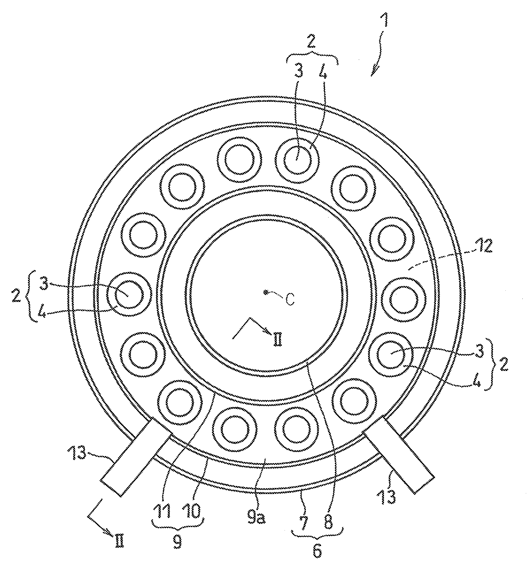
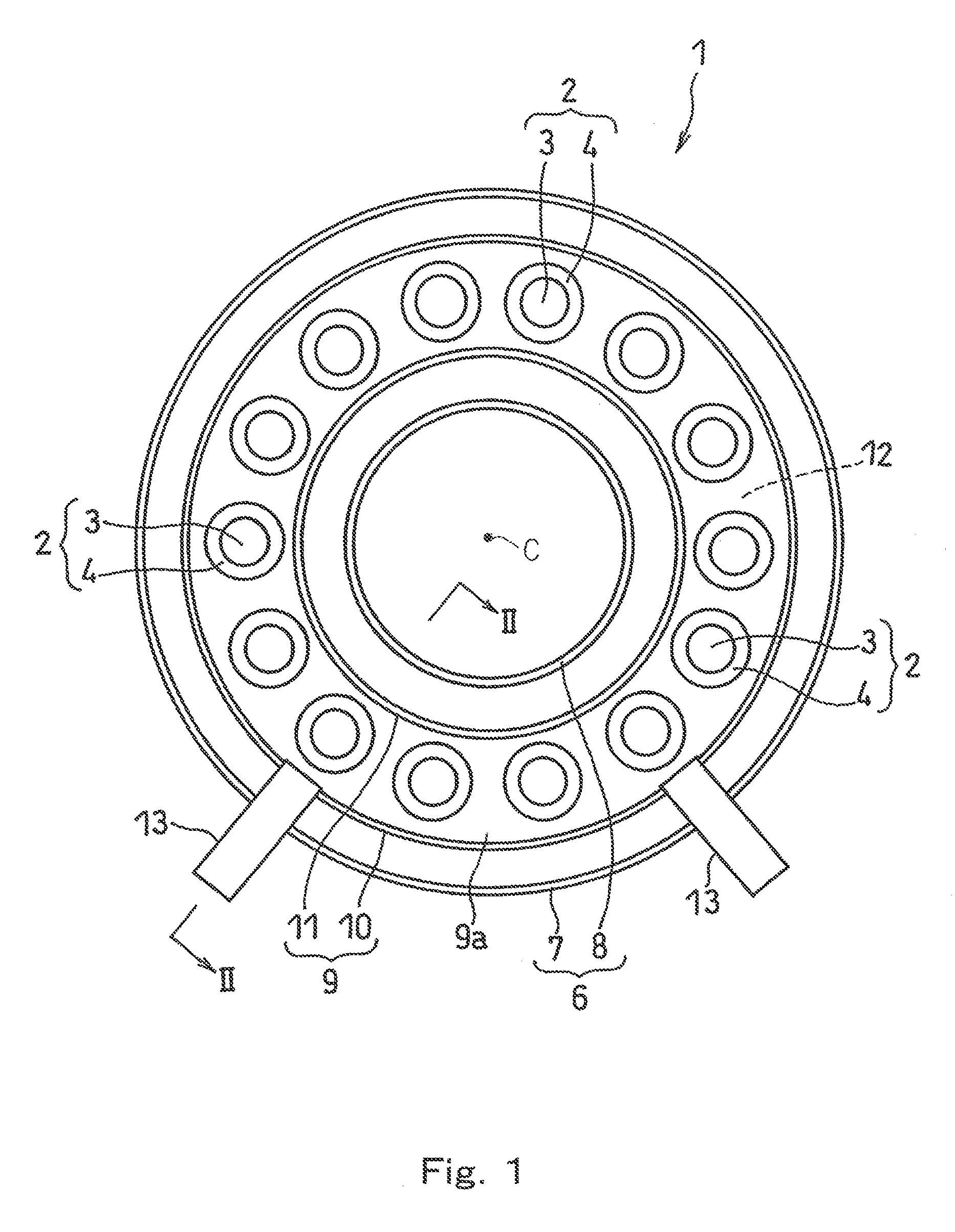
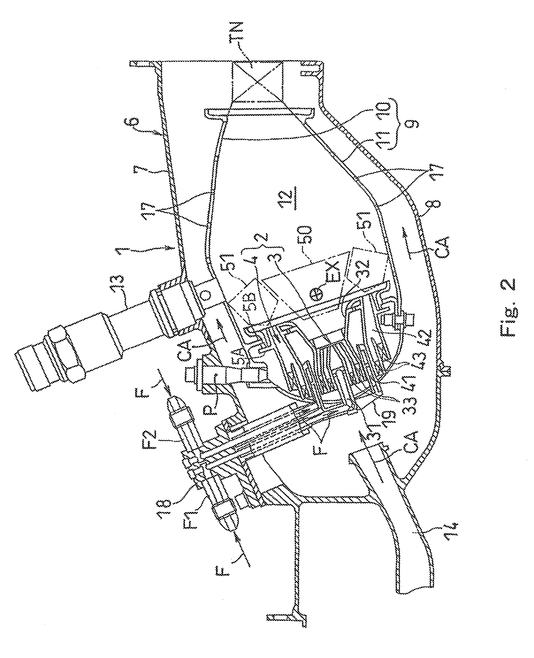
[0034]Hereinafter, a preferred embodiment of the present invention will be described with reference to the drawings. FIG. 1 shows a head portion of a combustor 1 of a gas turbine engine including a fuel supply device according to Embodiment 1 of the present invention. The combustor 1 is configured to combust an air-fuel mixture generated by mixing fuel with compressed air supplied from a compressor (not shown) in a gas turbine engine, and feed high-temperature and high-pressure combustion gas generated by the combustion to a turbine to drive the turbine.

[0035]The combustor 1 is an annular type and has a configuration in which a tubular inner casing 8 is disposed inward relative to a tubular outer casing 7 such that the center axis C of the gas turbine engine is a center of the inner casing 8. The outer casing 7 and the inner casing 8 constitute a combustor housing 6 having an annular inner space. In the annular inner space of the combustor housing 6, a tubular inner liner 11 is disp...


PUM


Abstract

A fuel supply device of a gas turbine engine is provided. The fuel supply device includes a fuel divider which divides fuel supplied from a collecting fuel passage to feed the fuel to a pilot fuel passage and to a main fuel passage. The fuel divider includes a movable member which is movable according to fuel pressure at the fuel entrance and opens and closes pilot ports and main ports according to a distance of the movement of the movable member. When the fuel pressure at the fuel entrance is not higher than a predetermined value, the fuel is supplied only to the pilot fuel passage, while when the fuel pressure at the fuel entrance is higher than the predetermined value, the fuel is supplied to the pilot fuel passage and to the main fuel passage.

Description

TECHNICAL FIELD[0001]The present invention relates to a fuel supply device of a gas turbine engine for supplying a fuel to a combustor including pilot burners and main burners.BACKGROUND ART[0002]For environment protection purposes, in gas turbine engines, strict environmental standards are set for the composition of emitted combustion exhaust gas. It is required that harmful substances such as nitrogen oxide (hereinafter expressed as NOx) are reduced from the exhaust gas. In large-sized gas turbines and engines for aircraft, a pressure ratio tends to be set high, because of the requirements of low fuel consumption and high power output. Correspondingly, air at an entrance of a fuel supply device tends to be placed in higher temperature and higher pressure conditions. With an increase in the temperature of the air at the entrance of the fuel supply device, a combustion temperature rises, which may undesirably result in an increase in the amount of NO in the exhaust gas.[0003]Under t...

Claims


Application Information

Patent Timeline
Patent Type & Authority Applications(United States)
IPC IPC(8): F02C7/22F02C7/232
CPCF02C7/228F02C7/232F23K5/06F23K2301/206F23N1/007F23K5/147F23N2037/02F23N2037/10F23R3/28F23R3/343Y02T50/672F23N2035/24F23N2235/24F23N2237/02F23N2237/10F23K2300/206Y02T50/60F02C9/34
Inventor OGATA, HIDEKIOHYAMA, KAZUHIKOHATANO, TOMOYUKISHIMIZU, AKIHIROMIWA, TOUYA
Owner KAWASAKI HEAVY IND LTD
Why Eureka
Try Eureka