Obstacle detection apparatus and method for detecting obstacle

a detection apparatus and obstacle technology, applied in the direction of vehicle position/course/altitude control, using reradiation, instruments, etc., can solve the problems of difficult to directly and visually confirm, difficult to park the vehicle appropriately, and low height of the wheel stopper, etc., to achieve a simple and inexpensive structure

Active Publication Date: 2013-08-06
NIPPON SOKEN +1
View PDF20 Cites 17 Cited by
  • Summary
  • Abstract
  • Description
  • Claims
  • Application Information

AI Technical Summary

Benefits of technology

[0005]In view of the above and other problems, it is an object of the present invention to produce an obstacle detection apparatus having a simple and inexpensive structure and configured to distinguish between a high obstacle, such as a pole and a wall, and a low obstacle, such as a wheel stopper, without closely approaching to an obstacle. It is another object of the present invention to produce a method for detecting an obstacle.

Problems solved by technology

In such a case, when a driver forgets to confirm whether a wheel stopper is located in a parking space in advance, it is hard to park the vehicle appropriately.
In addition, a wheel stopper, which is low in height from a road surface, is hard to be directly and visually confirmed.
It is noted that the obstacle detection apparatus of JP-A-2006-343309 includes multiple elements in an array form for recognizing a kind of an object and is expensive.

Method used


Image

  • Obstacle detection apparatus and method for detecting obstacle
  • Obstacle detection apparatus and method for detecting obstacle
  • Obstacle detection apparatus and method for detecting obstacle

Examples


first embodiment

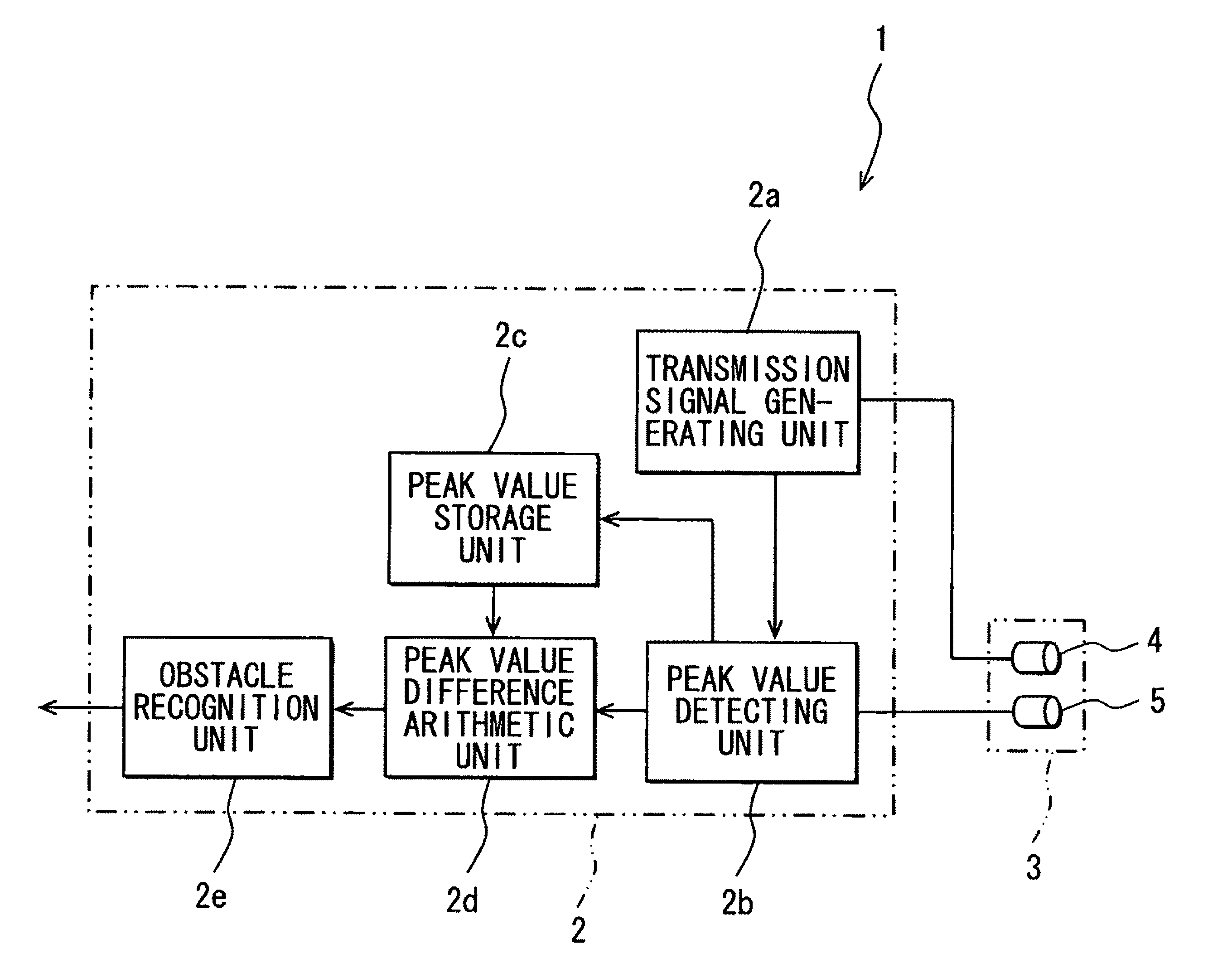
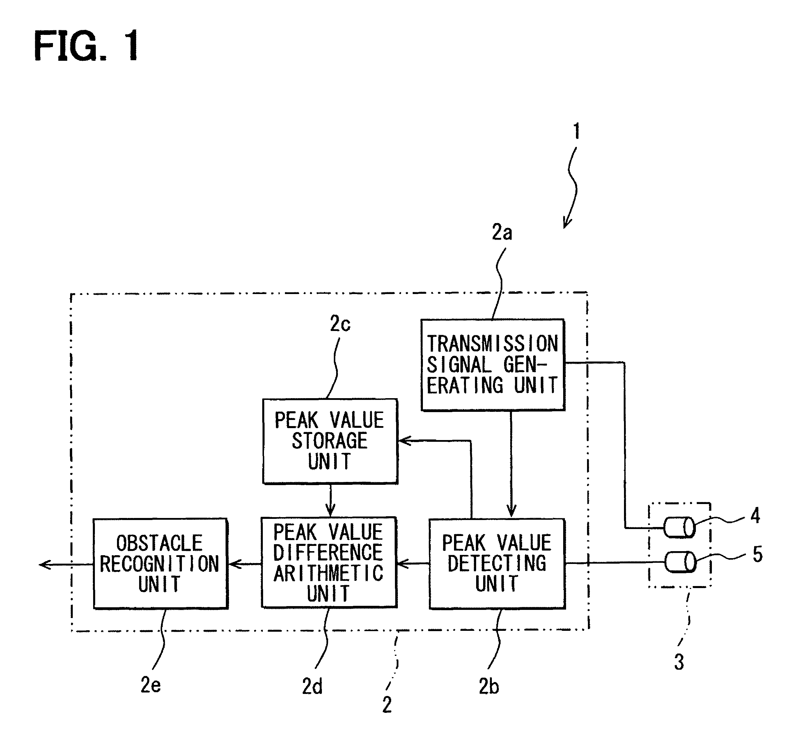
[0027]As follows, the present embodiment will be described with reference to FIGS. 1 to 5. FIG. 1 is a block diagram showing an electric connection of an obstacle detection apparatus 1, which includes an electronic control unit (ECU) 2 and a transmission and reception device 3. The ECU 2 mainly includes a control unit such as a microcomputer having a processing function. The ECU 2 further includes a storage circuit such as a ROM, a RAM, and / or a nonvolatile memory and an interface unit via which various kinds of data and the like are transmitted. The storage circuit prestores an obstacle recognition program.

[0028]As shown in FIG. 1, the ECU 2 has functional blocks for constituting an obstacle recognition program function. The ECU 2 includes functional blocks of a transmission signal generating unit 2a, a peak value detecting unit 2b, a peak value storage unit 2c, a peak value difference arithmetic unit 2d, and an obstacle recognition unit 2e. The transmission and reception device 3 ...

second embodiment

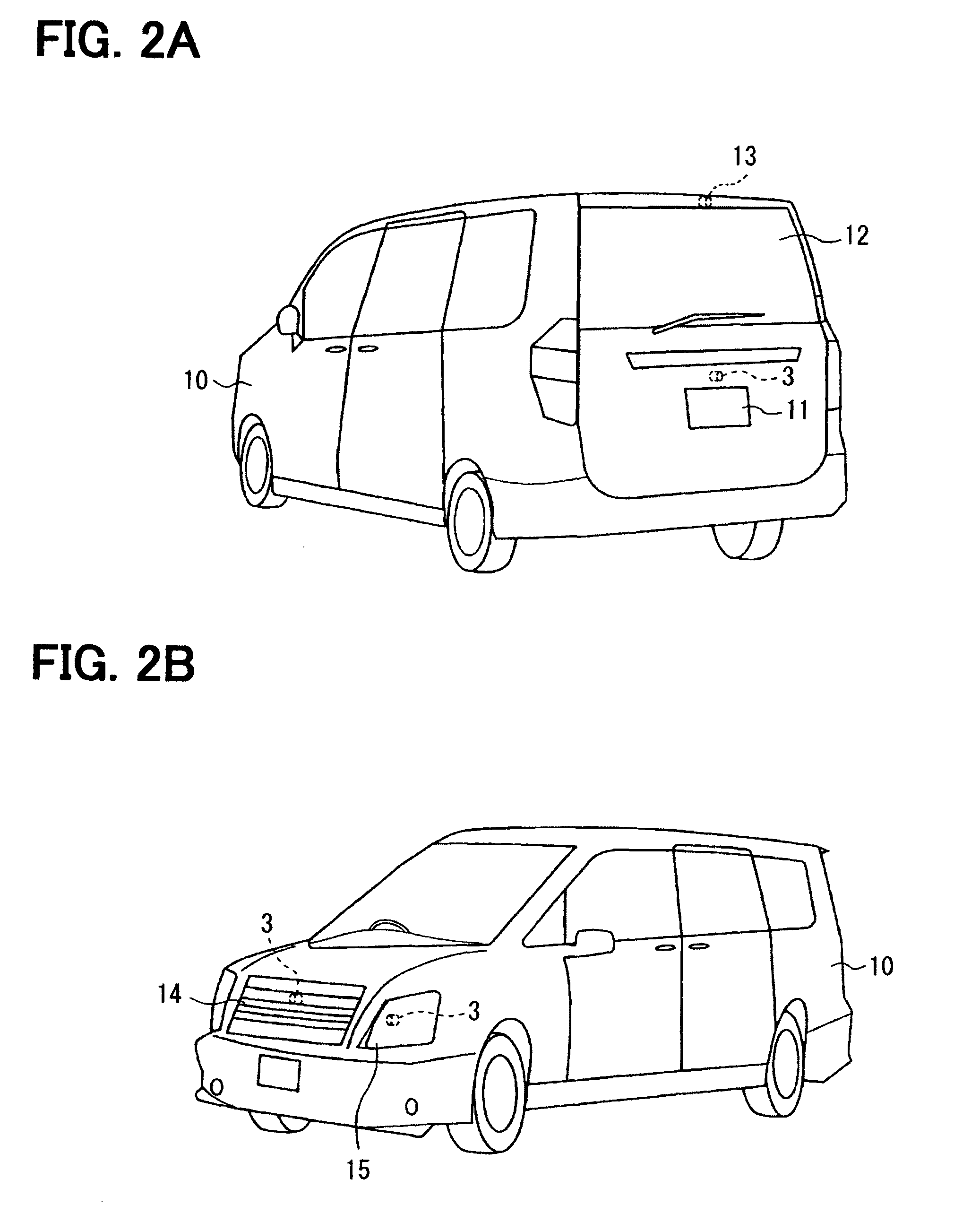
[0042]FIGS. 6, 7 relate to a second embodiment of the present invention. The present second embodiment is different from the first embodiment in an additional function to calculate a horizontal distance from a near-road-surface obstacle P when it is determined that a detected object is the near-road-surface obstacle P. The position of the transmission and reception device 3 is located at an upper position of the license plate 11 of the automobile 10 or in the washer nozzle 13 of the rear window. Therefore, the position of the transmission and reception device 3 and a detected object such as a near-road-surface obstacle P with a low height have a difference therebetween in height in a vertical direction. Accordingly, even when a linear distance from a detected object can be detected, an error arises in the horizontal distance from a detected object when being seen from the automobile 10. Therefore, in the present embodiment, an error in a distance attributed to a vertical distance be...

third embodiment

[0047]FIGS. 8 to 11 relate to a third embodiment of the present invention. The present third embodiment is different from the above embodiments in an additional display device (display unit, indication portion) 16 as a display unit and an additional speaker (sounding unity 17 both of which function as information units. In the present embodiment, a driver or a passenger is notified of whether a detected object is a near-road-surface obstacle P or an other obstacle Q using the display device 16 and / or the speaker 17 with an indication and / or a voice.

[0048]The ECU 2 executes the obstacle recognition program and performs an information operation according to a determination result when determining that a detected object is a near-road-surface obstacle P or an other obstacle Q. In the information operation, the speaker 17 causes sound differently in accordance with a notification pattern shown in FIG. 9, for example, so as to inform a kind of a detected object.

[0049]In the first notific...


PUM


Abstract

A transmission and reception device is located at a predetermined height on a movable object and directed toward an outside. The transmission and reception device includes a transmission unit for repeatedly transmitting sensing waves at a predetermined interval and a reception unit for receiving reflective waves of the sensing waves from a detected object. A peak value detecting unit detects peak values of the received reflective waves and stores the detected peak values. A difference arithmetic unit calculates a difference in the detected peak values with movement of the movable object closer to the detected object. An object determination unit determines the detected object to be a near-road-surface obstacle, which is close to a road surface, when the difference is a negative value. The object determination unit determines the detected object to be an other obstacle than the near-road-surface obstacle when the difference is a positive value.

Description

CROSS REFERENCE TO RELATED APPLICATIONS[0001]This application is based on and incorporates herein by reference Japanese Patent Application No. 2009-45803 filed on Feb. 27, 2009.FIELD OF THE INVENTION[0002]The present invention relates to an obstacle detection apparatus for detecting an obstacle in a movable direction of a movable object. The present invention relates to a method for detecting an obstacle.BACKGROUND OF THE INVENTION[0003]When a vehicle (movable object) is parked in a garage, a parking lot, or the like, it is necessary to recognize a kind of an obstacle, such as a wheel stopper, a pole, or a wall, for appropriately park the vehicle. In particular, when a vehicle is parked by moving the vehicle to a parking space backward, recognition of a kind of an obstacle is significantly important. In such a case, when a driver forgets to confirm whether a wheel stopper is located in a parking space in advance, it is hard to park the vehicle appropriately. In addition, a wheel sto...

Claims


Application Information

Patent Timeline
Patent Type & Authority Patents(United States)
IPC IPC(8): G01S15/00G01S13/00G08B1/08G05D1/02B60Q1/00G08G1/01G08G1/16G01S7/40G01S15/931
CPCG01S7/5273G01S7/539G01S15/87G01S15/931G01S15/42G01S2015/939G01S15/46
Inventor AKIYAMA, KEIKOMATSUURA, MITSUYASUMATSUOKA, HISANAGAOKUDA, YASUYUKIARIYOSHI, HIROMI
Owner NIPPON SOKEN
Why Eureka
Try Eureka