Inverter transformer

a technology of inverter transformer and transformer body, which is applied in the direction of transformer/inductance details, fixed transformers, inductances, etc., can solve the problems of pushed up production costs and difficult production, and achieve the effect of simple and inexpensive structure, convenient adjustment, and efficient coupling to on

Inactive Publication Date: 2008-11-25
MINEBEA CO LTD
View PDF20 Cites 15 Cited by
  • Summary
  • Abstract
  • Description
  • Claims
  • Application Information

AI Technical Summary

Benefits of technology

[0018]Also, the present invention, which is suitably applied to an inverter transformer with four to six outputs, may further be applied advantageously to a large backlight device, for example, for use in, an LCD television, where the number of outputs (that is the number of bobbins having a secondary winding) of an inverter transformer is large, and therefore the space efficient structure exhibits its advantageous effects sufficiently.
[0019]In the aspect of the present invention, the insulation distance setting means may be constituted by extensions formed integrally at one side of the bobbin, the two bobbins of the first bobbin pair may be coupled to each other such that the extensions of one bobbin are engaged with a non-extended plain side of the other bobbin, and the two bobbins of the second bobbin pair may be coupled to each other with their respective non-extended plain sides engaging with each other. Alternatively, in the aspect of the present invention, the insulation distance setting means may be constituted by a spacer member made of a non-magnetic material and formed separately from the bobbin, the two bobbins of the first bobbin pair may be coupled to each other such that one side of one bobbin is engaged with one side of the spacer member and one side of the other bobbin is engaged with the other side of the spacer member, and the two bobbins of the second bobbin pair may be coupled to each other with their respective sides engaging with each other.
[0020]With the insulation distance setting means structured as described above, an inverter transformer can be produced in a simple and inexpensive structure. Also, the plurality of bobbins can be securely and efficiently coupled to one another with or without some spacer members. And, if the spacer member is used as the insulation distance setting means, the distance required for securing a withstand voltage between the secondary windings can be readily adjusted by changing the width dimension of the spacer member. In the aspect of the present invention, the inverter transformer may be a leakage transformer, whereby the leakage inductance of the inverter transformer functions as a ballast when lighting CCFLs connected at the secondary side of the inverter transformer.Effect of the Invention
[0021]According to the present invention, with the structure described above, a small size and low cost inverter transformer for lighting multiple lamps can be provided which has a plurality of outputs including reverse polarity output voltages while ensuring a reliable insulation performance.

Problems solved by technology

While one inverter transformer of FIG. 12 can drive a plurality of CCFLs with a double voltage as described above, the magnetic core 250 has a complicated structure making it difficult to produce, which pushes up production cost.
Under such a core arrangement, if any one of the output voltages induced at the secondary windings 125a, 125b and 125c is to have its polarity reversed from the polarity of the other output voltages, the withstand voltage between two adjacent secondary windings at which reverse polarity output voltages are induced is not sufficient, especially at the high potential side, resulting in that a corona discharge or spark discharge occurs possibly causing ignition in some cases.

Method used


Image

  • Inverter transformer
  • Inverter transformer
  • Inverter transformer

Examples


second embodiment

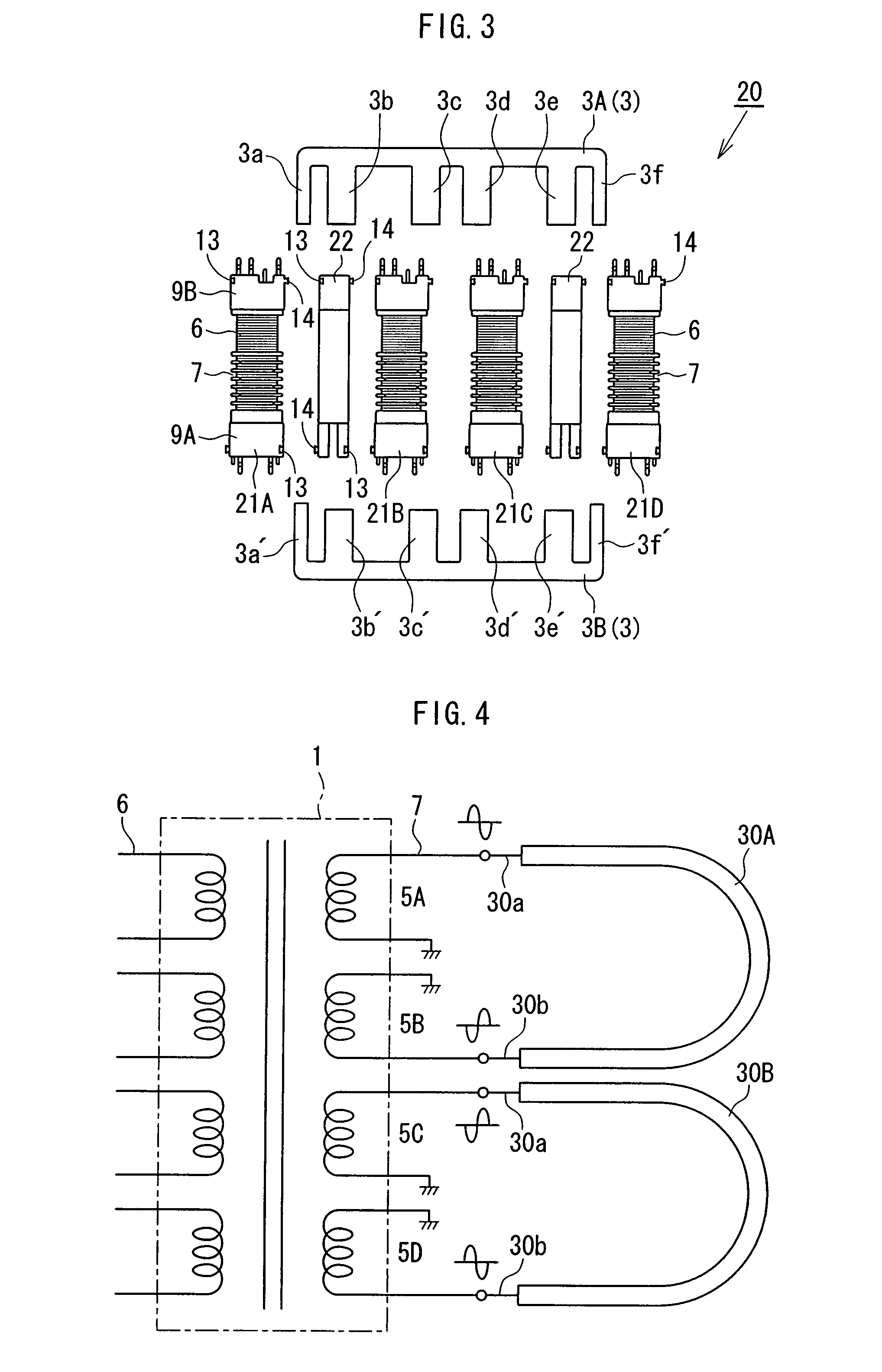
[0047]the present invention will be described with reference to FIG. 3. Referring to FIG. 3, an inverter transformer 20 according to the second embodiment includes a magnetic core assembly 3 composed of two magnetic cores 3A and 3B which are identical with those of the inverter transformer 1 according to the first embodiment, and has a performance property equivalent to that of the inverter transformer 1. The inverter transformer 20 differs from the inverter transformer 1 mainly in that four bobbins 21A to 21D are configured identically with one another, and that a spacer member 22 is used as an insulation distance setting means. For example, the bobbin 5B / 5D of FIG. 2 may be used for the four bobbins 21A to 21D.

[0048]The spacer member 22 is made of a non-magnetic material, preferably of the same material as the bobbins 21A to 21D, for example, liquid crystal polymer. The spacer member 22 has a recess 13 at one side (toward the left in the figure) of one end (upper in the figure) th...


PUM

PropertyMeasurementUnit
output voltagesaaaaaaaaaa
distanceaaaaaaaaaa
insulation distanceaaaaaaaaaa

Abstract

An inverter transformer for lighting multiple discharge lamps is provided which has a plurality of output voltages including reversed polarity output voltages while ensuring a reliable insulation performance, and which is produced in a small size and at a low cost. An inverter transformer includes a magnetic core assembly, and a plurality of bobbins each having a primary winding and a secondary winding wound therearound. Adjacent two bobbins of the bobbins constitute either a first bobbin pair which are provided with respective secondary windings at which output voltages having their polarities reversed from each other are induced, or a second bobbin pair. An insulation distance setting means are provided between the two bobbins so that the distance between the secondary windings disposed at the two bobbins and of the first bobbin pair is larger than the distance between the secondary windings disposed at the two bobbins of the second bobbin pair.

Description

BACKGROUND OF THE INVENTION[0001]1. Field of the Invention[0002]The present invention relates to an inverter transformer for lighting a discharge lamp as a light source of backlight device for a liquid crystal display apparatus, and particularly to an inverter transformer to provide a plurality of outputs for lighting a plurality of discharge lamps.[0003]2. Description of the Related Art[0004]A liquid crystal display (LCD) apparatus, which is used for electronic appliances, such as a television, a personal computer, and the like, does not emit light by itself, and therefore a lighting system, such as a backlight device, is required. A discharge lamp is used as a light source for such a backlight device, and a cold cathode fluorescent lamp (CCFL) is typically employed as a discharge lamp. Recently, the screen size of an LCD apparatus, for example, an LCD television, is becoming larger and larger, and a plurality of CCFLs are used in order to achieve the high brightness level required...

Claims


Application Information

Patent Timeline
Patent Type & Authority Patents(United States)
IPC IPC(8): H01F27/30
CPCH01F38/10H05B41/2822H01F30/04
Inventor SUZUKI, MITSUAKINONOYAMA, KOICHIARAO, YOSHINORI
Owner MINEBEA CO LTD
Why Eureka
Try Eureka