
Connector member for electrical connections through a wall of a fuel tank, particularly for the LPG fuel tank of a motor vehicle

a fuel tank and connector technology, applied in the direction of container discharging methods, coupling device connections, applications, etc., can solve the problems of relatively brittle glass disks b>7/b>, high production costs, and similar problems, and achieve the effect of efficient electrical connection and structure of electrical connectors

Inactive Publication Date: 2006-07-04
CENT RICERCHE FIAT SCPA
View PDF4 Cites 16 Cited by
  • Summary
  • Abstract
  • Description
  • Claims
  • Application Information

AI Technical Summary

Benefits of technology

[0009]The purpose of the present invention is to provide a connector member for electrical connections through a wall of the fuel tank of a motor vehicle that will be free from the drawbacks mentioned above. It is, in particular, a purpose of the invention to provide a connector member that, on the one hand, will be able to guarantee hermetic sealing of the tank even in the presence of a pressure difference between the internal cavity of the tank and the external environment, and, on the other hand, will have a relatively simple and inexpensive structure, which is resistant and reliable in operation.
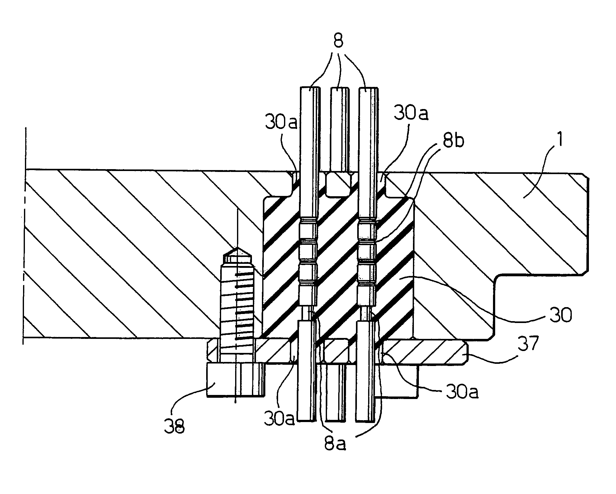
[0013]Thanks to the characteristics referred to above, the electrical cable-lead connector of the invention is able, on the one hand, to ensure efficient electrical connection of the electrical components arranged within the tank with the external electrical lines and, on the other hand, to guarantee hermetic sealing of the tank also in the presence of major pressure jumps between the internal cavity of the tank and the external environment. The structure of the electrical connector according to the invention is moreover relatively simple and inexpensive to produce. Finally, the device according to the invention is not subject to the risks of failure that occur, instead, in the case of the known art on account of the fragility of the element made of glass described above.

Problems solved by technology

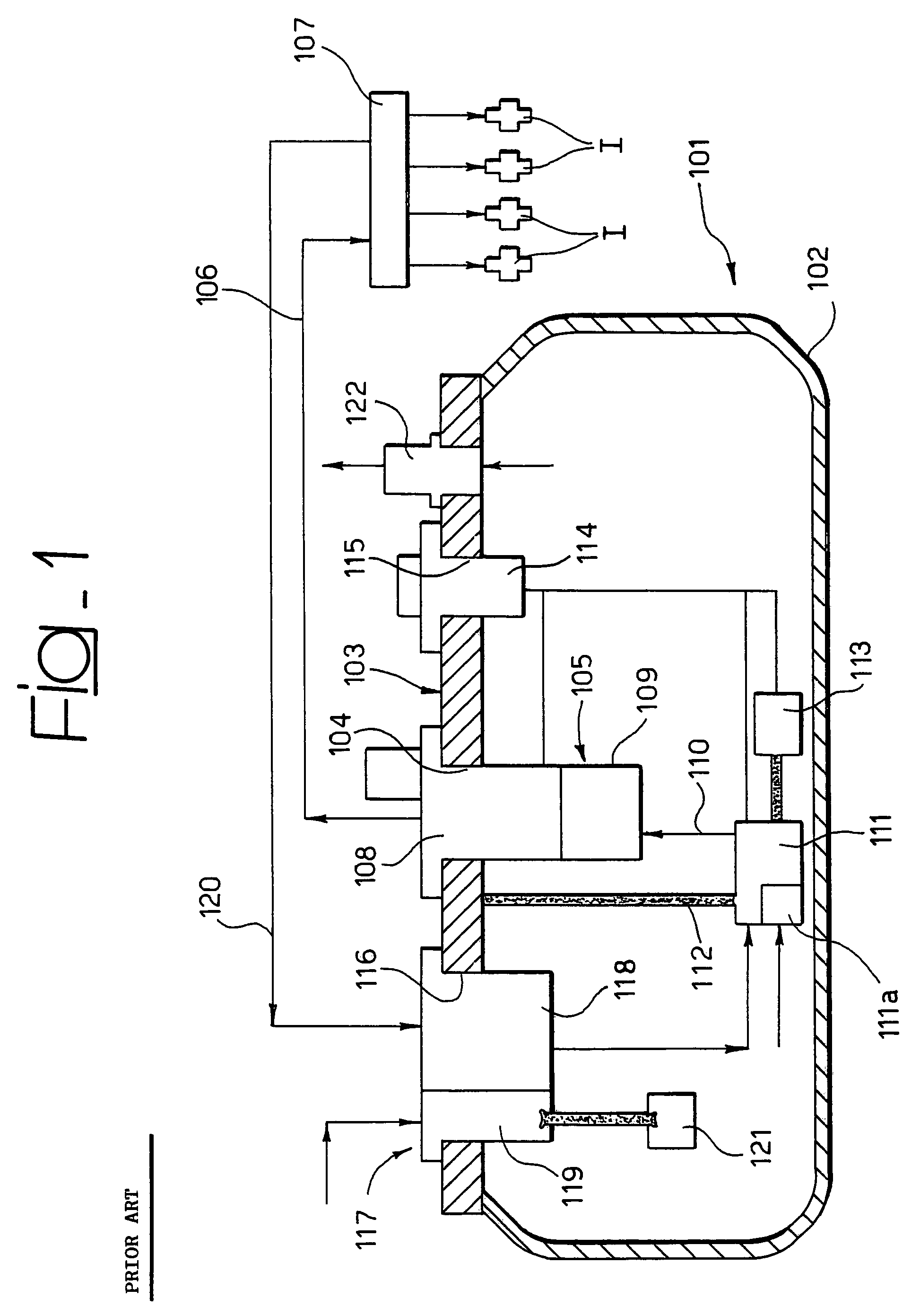
Of course, the same problem may also arise in supply systems which use different fuels, such as tanks for methane supply systems or in general any other fuel tank in which it is necessary, on the one hand, to enable electrical connection with components arranged within the tank and, on the other hand, guarantee hermetic sealing of the tank itself, in particular in the presence of a pressure jump between the inside and the outside.
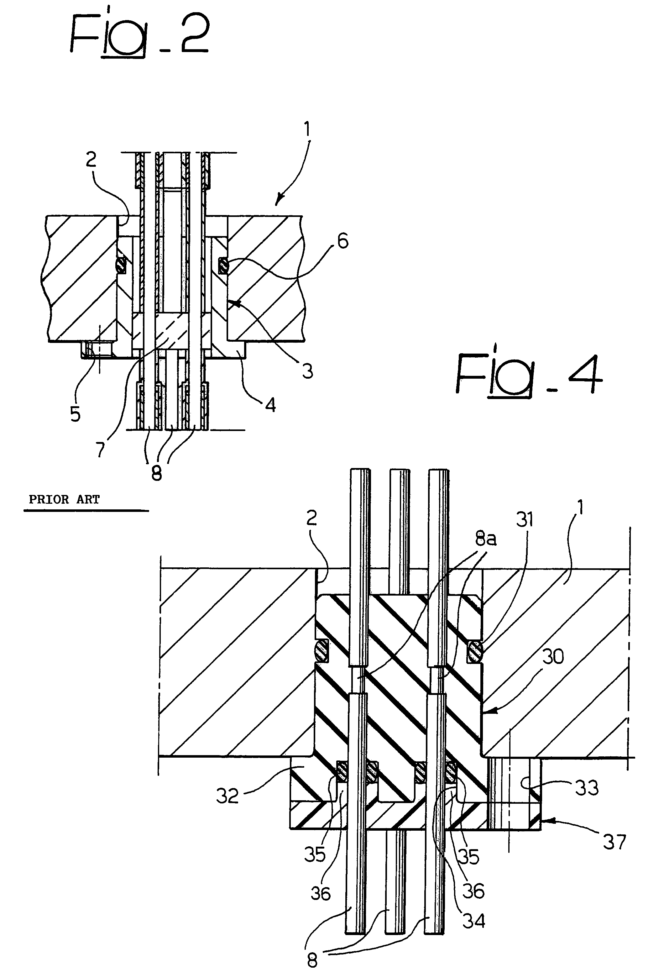
The drawback of said known solution lies in the fact that the glass disk 7 is relatively brittle and is subject to the risk of cracking or fracturing resulting, for example, from thermal shock or possible careless manipulation of the tank or its components, particularly in the assembly and installation step.
A further drawback lies in the fact that the known devices of the type referred to above are relatively complex and costly to produce.

Method used


Image

  • Connector member for electrical connections through a wall of a fuel tank, particularly for the LPG fuel tank of a motor vehicle
  • Connector member for electrical connections through a wall of a fuel tank, particularly for the LPG fuel tank of a motor vehicle
  • Connector member for electrical connections through a wall of a fuel tank, particularly for the LPG fuel tank of a motor vehicle

Examples


Embodiment Construction

[0020]In FIG. 1, the reference number 101 designates as a whole an LPG fuel tank built according to the known art, for supplying LPG to a plurality of injectors I associated to the various cylinders of the engine. The tank 101 has a hollow structure 102 built so as to guarantee tightness at the working pressures expected for a system of the type in question. The hollow structure 102 has a top opening closed by a service flange 103 carrying the various connector elements and providing connection of the tank to the supply system. For this purpose, the tank 101 has a first through opening 104, through which there is installed the structure of an assembly 105 connected to a line 106 for delivery of the LPG to a distribution manifold or rail 107, which distributes the LPG between the various injectors I. The assembly 105 includes a shut-off solenoid valve 108, which is designed to close, so interrupting communication of the tank with the outside environment in pre-determined emergency co...


PUM


Abstract

A fuel tank for motor vehicles, for example an LPG fuel tank, contains inside it at least one electrical component and has a wall or a plate bearing at least one connector for connection of the electrical component with an electrical line external to the tank. The electrical connector has a body made of synthetic material or of elastomer material directly moulded on one or more conductor pins so as to guarantee hermetic sealing of the tank even in the presence of a pressure jump between the internal cavity of the tank and the external environment. In the case where the body of the connector is made of synthetic material, it bears seats for seal rings made of elastomer material. In the case where it is made of elastomer material, it guarantees directly the function of tightness. In either case, there are provided means for exerting an axial compressive force on the part that performs the tightness function.

Description

BACKGROUND OF THE INVENTION[0001]The present invention relates to fuel tanks for motor vehicles, in particular to Liquid Petroleum Gas (LPG) fuel tanks for motor vehicles.[0002]For some time now the present applicant has studied and developed systems of supply via injection of LPG for engines of motor vehicles, which use a plurality of LPG injectors associated to the cylinders of the engine, which are supplied with LPG coming from a tank.[0003]Supply systems of the type referred to above are, for example, described and illustrated in the European patent No. EP-B-0 725 205 and in the European patent No. EP-B-0 922 851 in the name of the present applicant, as well as in the corresponding patents Nos. U.S. Pat. No. 5,592,924 and U.S. Pat. No. 6,050,237. The present applicant has also filed various patent applications regarding the tank of the supply system in question and to the various electrical and hydraulic components that are associated thereto. Typically, the tank has a hollow bo...

Claims


Application Information

Patent Timeline
IPC IPC(8): H02G3/00F17C13/04H01R13/52H01R13/74
CPCF17C13/04H01R13/521H01R13/748H01R13/5202Y10T16/063H01R2201/26F17C2205/0326F17C2205/0332F17C2221/035F17C2227/0135F17C2227/0178F17C2250/0417F17C2265/066F17C2270/0168Y10T16/05
Inventor RICCO, MARIODE MATTHAEIS, SISTO LUIGIAMORESE, CLAUDIO
Owner CENT RICERCHE FIAT SCPA
Learn More