Semiconductor package and method of fabricating the same

Active Publication Date: 2014-01-16
SILICONWARE PRECISION IND CO LTD
View PDF9 Cites 5 Cited by
  • Summary
  • Abstract
  • Description
  • Claims
  • Application Information

AI Technical Summary

Benefits of technology

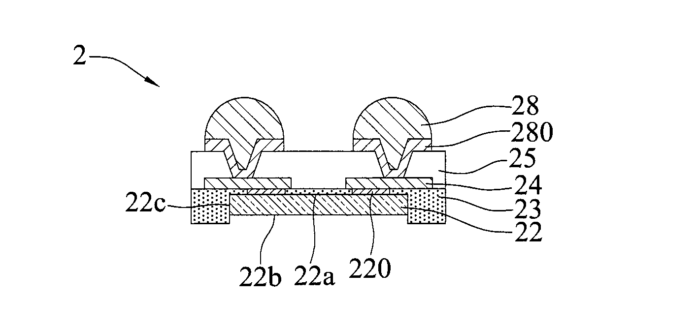
[0024]According to the present invention, since being formed only on the chip areas instead of on the overall carrier as in the prior art, the connection units are prevented from expanding or contracting as temperature changes. The

Problems solved by technology

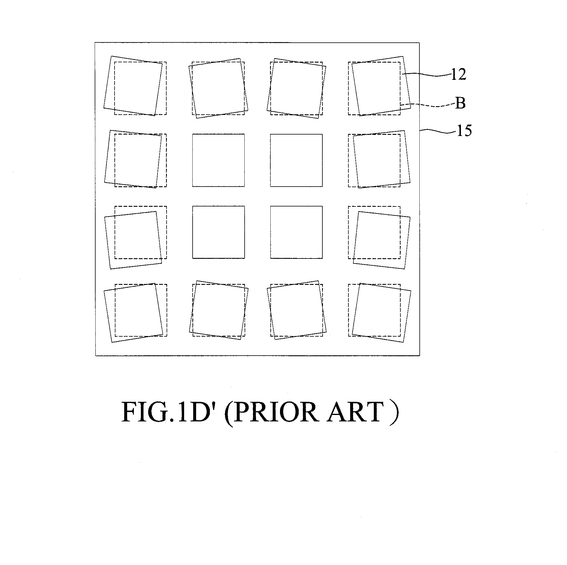
The larger the size of the carrier 10 is, the greater the positional deviation of the semiconductor elements 12 becomes, thus adversely

Method used


Image

  • Semiconductor package and method of fabricating the same
  • Semiconductor package and method of fabricating the same
  • Semiconductor package and method of fabricating the same

Examples


Example

[0030]FIGS. 2A to 2G are schematic cross-sectional views showing a method of fabricating a semiconductor package 2 according to a first embodiment of the present invention.

[0031]Referring to FIGS. 2A and 2A′, a carrier 20 is provided with a plurality of chip areas A defined thereon. A plurality of connection units 21 are formed on the chip areas A.

[0032]In an embodiment, the connection units 21 are made of an adhesive material and formed by screen printing or dispensing. Alternatively, the connection units 21 are made of a photosensitive adhesive material and formed by patterning.

[0033]Referring to FIG. 2B, a plurality of semiconductor elements 22 are disposed on the connection units. Each of the semiconductor elements 22 has an active surface 22a with a plurality of electrode pads 220, a non-active surface 22b opposite to the active surface 22a, and side surfaces 22c connecting the active surface 22a and the non-active surface 22b.

[0034]Each of the semiconductor elements 22 is dis...


PUM


Abstract

A method of fabricating a semiconductor package is provided, including: providing a carrier having a plurality of chip areas defined thereon, and forming a connection unit on each of the chip areas; disposing a semiconductor element on each of the connection units; forming an insulating layer on the carrier and the semiconductor elements; and forming on the insulating layer a circuit layer electrically connected to the semiconductor elements. Since being formed only on the chip areas instead of on the overall carrier as in the prior art, the connection units are prevented from expanding or contracting during temperature cycle, thereby avoiding positional deviations of the semiconductor elements.

Description

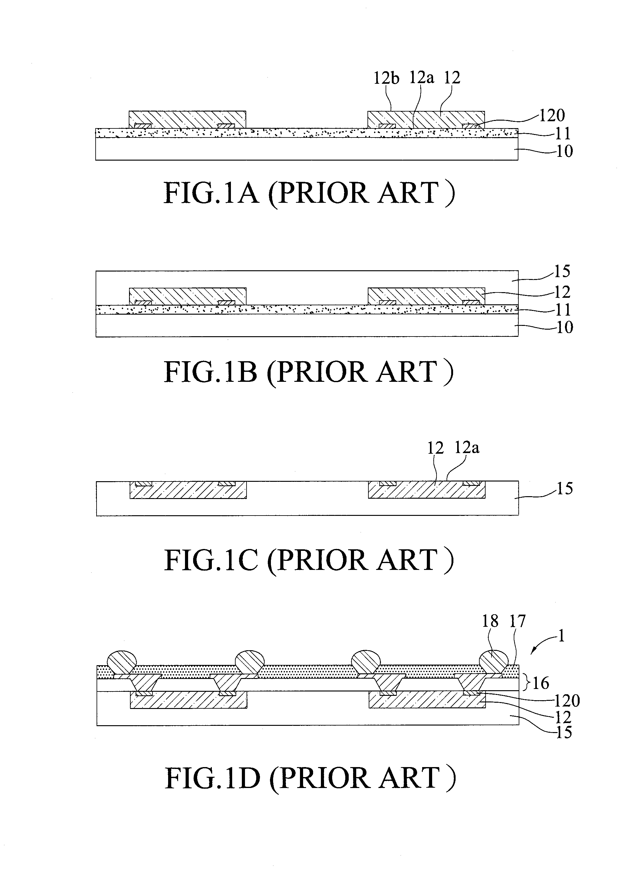
BACKGROUND OF THE INVENTION[0001]1. Field of the Invention[0002]The present invention relates to semiconductor packages and methods of fabricating the same, and, more particularly, to a wafer-level semiconductor package and a method of fabricating the same.[0003]2. Description of Related Art[0004]Along with the rapid development of electronic industries, electronic products are developed towards multi-function and high electrical performance. Accordingly, wafer level packaging (WLP) technologies have been developed to meet the miniaturization requirement of semiconductor packages.[0005]FIGS. 1A to 1D are schematic cross-sectional views showing a method of fabricating a wafer-level semiconductor package 1 according to the prior art.[0006]Referring to FIG. 1A, a thermal release tape 11 is formed on a carrier 10, and a plurality of semiconductor elements 12 are disposed on the thermal release tape 11. Each of the semiconductor elements 12 has an active surface 12a with a plurality of e...

Claims


Application Information

Patent Timeline
IPC IPC(8): H01L23/498H01L21/50
CPCH01L24/19H01L24/96H01L2924/18162H01L2224/12105H01L2224/215H01L2224/211H01L2224/2101H01L21/568H01L24/03H01L24/05H01L24/11H01L24/13H01L24/20H01L2224/0401H01L2224/04105H01L2224/05558H01L2224/13022H01L2224/131H01L2224/96H01L23/3185H01L2924/014H01L2924/00014H01L2224/19H01L2224/11H01L2224/03H01L21/00H01L2224/82H01L2924/15153
Inventor LEE, MENG-TSUNGCHANG, CHIANG-CHENGCHIU, SHIH-KUANG
Owner SILICONWARE PRECISION IND CO LTD
Why Eureka
Try Eureka