Pipeline scrolling device

A pipeline reel and tube reel technology, applied in the field of pipeline reel, can solve the problems of weak fastening, wear and damage of integral structural components, burning of point shaft cores, etc., so as to achieve convenient, fast and safe installation, convenient maintenance and disassembly, and extended use. effect of life

Inactive Publication Date: 2015-06-10
广州市强生信达贸易有限公司
View PDF10 Cites 5 Cited by
  • Summary
  • Abstract
  • Description
  • Claims
  • Application Information

AI Technical Summary

Problems solved by technology

If the installation and positioning of a certain part is inaccurate, it will easily cause problems in the quality of the product, and it will be easily damaged by machinery during use and operation.
It is complex and difficult to assemble and disassemble, and it is difficult to ensure the concentricity between the reel and the central fixed shaft and the housing, and the swing position is large, resulting in weak engagement of the stop part of the self-locking pawl and wear and damage of the overall structural components
3. The O-ring seal at the free end of the water-air rotary conversion shaft is scratched when it passes through the inner opening of the radial through hole during product installation, maintenance and disassembly, which makes it difficult to ensure the sealing performance
4. The rotating shaft sleeve and the fixed shaft core are position

Method used


Image

  • Pipeline scrolling device
  • Pipeline scrolling device
  • Pipeline scrolling device

Examples


Embodiment Construction

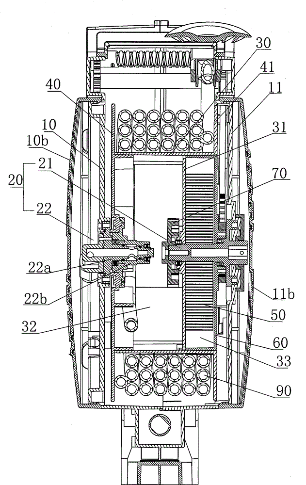
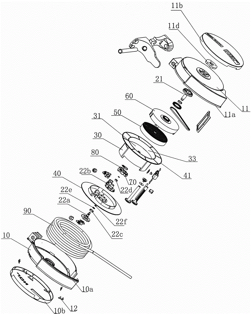
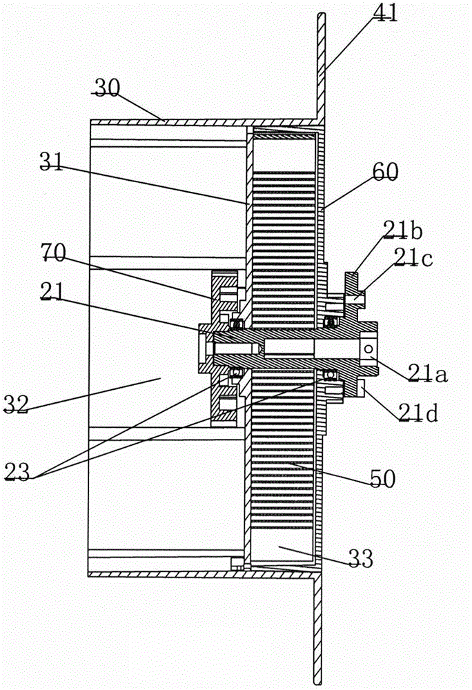
[0062] Such as Figure 1 to Figure 18As shown, a pipeline reel of the present invention includes left and right housings 10, 11, a shaft center 20, a reel tube 30, left and right reels 40, 41 and clockwork springs 50 on both sides of the reel tube 30, and the reel tube The tube 30 is positioned between the left and right shells 10, 11 through the axis 20, the axis 20 includes the left and right independent rotation conversion shaft 22 and the spring spring shaft 21, and the right side of the coil tube 30 is provided with a radial partition The plate 31 asymmetrically separates the independent large and small chambers 32, 33. The small chamber 33 on the right is provided with a cylindrical box 60 matching it, and the clockwork spring shaft 21 is arranged on the winding tube. The right side of 30 is interspersed in the box body 60, the right end is fixed with the right housing 11, and the left end extends in the large chamber 31 to set a fixed ratchet 70, and the radial partitio...


PUM


Abstract

The invention relates to a pipeline scrolling device. The pipeline scrolling device comprises a left shell, a right shell, a shaft core, a reelpipe barrel, a left reeling disc, a right reeling disc and a power spring, wherein the left reeling disc and the right reeling disc are arranged on the two sides of the reelpipe barrel; the reelpipe barrel is positioned between the left shell and the right shell through the shaft core; the shaft core comprises a power spring shaft and a rotating conversion shaft which are independently arranged on the left part and the on the right part; a large chamber and a small chamber, which are independent and formed through dissymmetric dividing of a radial partition board, are arranged on one side of the interior of the reelpipe barrel; a cylinder-shaped box body matched with the small chamber is arranged in the small chamber in a buckling manner; the power spring shaft is arranged on the right side of the reelpipe barrel and is inserted in the box body, the right end of the power spring shaft is fixed with the left shell, and the left end of the power spring shaft extends into the large chamber to set and fix a ratchet wheel; a self-locking pawl arranged on the radial partition board is buckled with the ratchet wheel; the power spring is positioned in the box body, the inner end of the power spring is connected with the power spring shaft, and the outer end of the power spring is fixedly connected with the barrel wall of the box body; positioning is performed and rotation conversion of steam pipelines or circuits is formed between the left side of the reepipe barrel and the left shell through the rotating conversion shaft.The pipeline scrolling device realizes the technical effect of coaxial double-pass pipe rotating conversion, and has the advantages of simple structure, smooth operation, high reliability and higher safety in use.

Description

technical field [0001] The invention relates to a pipeline reel for winding water and air pipes and cables. Background technique [0002] Existing automatic pipeline reels and automatic cable reels are generally composed of left and right housings, reels positioned between the left and right housings through fixed shafts, spring coil springs, self-locking pawls, and reels on both sides of the reel. It is widely used in the terminal operation of water, gas and electric pipelines in auto repair. 1. Due to the harsh environment of the work site, the reel used for pulling out mopping the floor is stained with dust, grease, paint and sewage and other substances. When it is recycled into the pipeline reel, it is easy to contaminate the internal working structural parts, especially the reel. The mainspring coil spring, self-locking pawl and water-gas or electric rotation conversion mechanism are easy to cause mechanical damage. The clockwork spring caused by the infiltration of s...

Claims


Application Information

Patent Timeline
IPC IPC(8): B65H75/44B65H75/48
Inventor 邱强生
Owner 广州市强生信达贸易有限公司
Why Eureka
Try Eureka