
Stator and rotary motor comprising same

A technology for rotating electrical machines and stators, which is applied to the static parts of the magnetic circuit, the shape/style/structure of the magnetic circuit, etc., which can solve the problems of bolt fastening force reduction, varnish insulation deterioration, fatigue, etc., and improve fastening reliability sexual effect

Inactive Publication Date: 2019-09-17
HONDA MOTOR CO LTD
View PDF3 Cites 3 Cited by
  • Summary
  • Abstract
  • Description
  • Claims
  • Application Information

AI Technical Summary

Problems solved by technology

[0004] Typically, the varnish applied to the stator coils suffers from insulation degradation or "fatigue" (deformation) over time
[0005] When the varnish permeates to the periphery of the fastening hole (fastening part) of the laminated electrical steel sheet, the fastening force of the bolt fastening may decrease due to the change of the varnish over time.

Method used


Image

  • Stator and rotary motor comprising same
  • Stator and rotary motor comprising same
  • Stator and rotary motor comprising same

Examples


Embodiment Construction

[0035] Hereinafter, embodiments of the present invention will be described in detail with reference to the drawings.

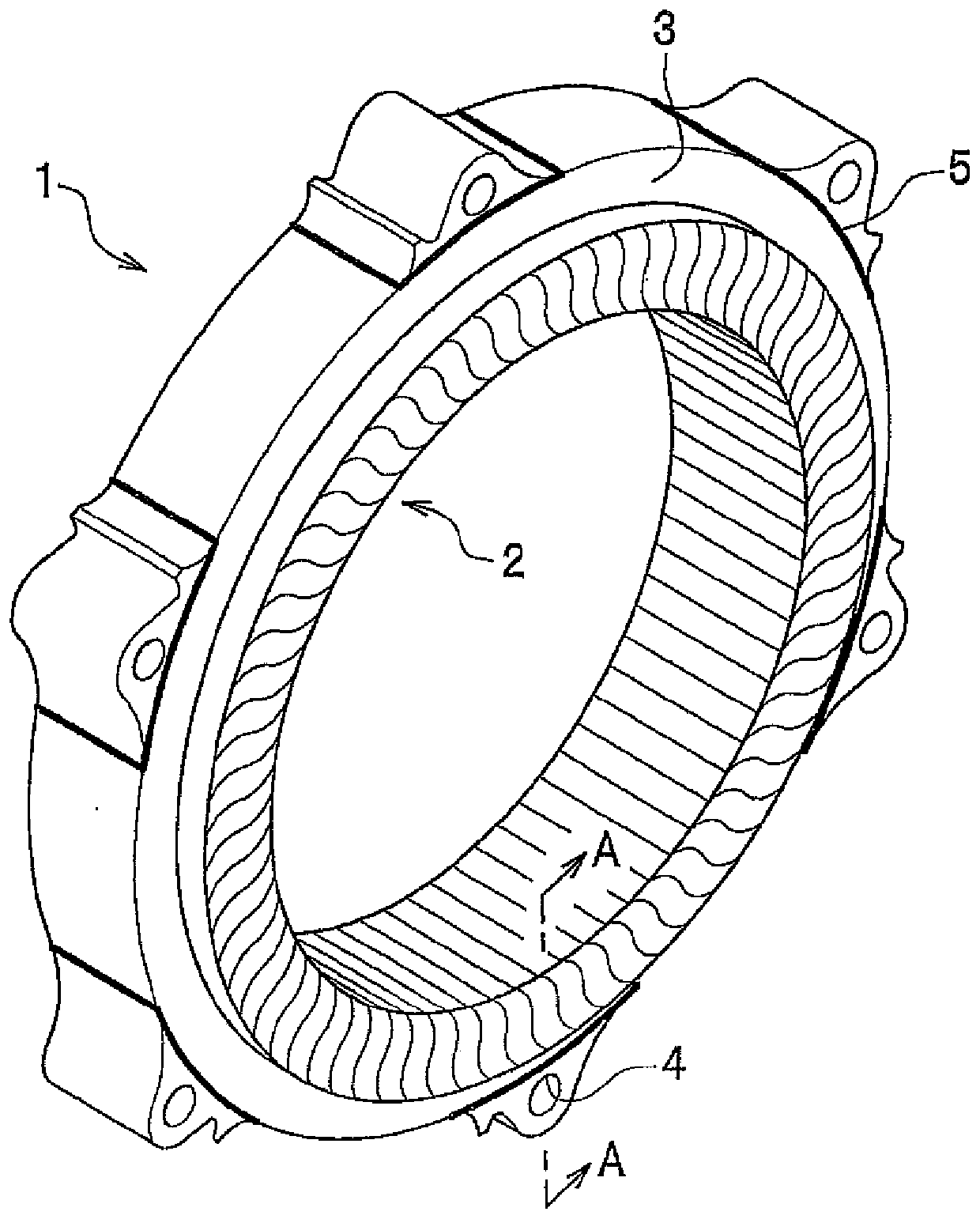
[0036] First, according to figure 1 Is a perspective view to explain the schematic structure of the stator 1 of the embodiment.

[0037] Here, the rotating electric machine having the stator 1 of the embodiment operates as a motor or a generator of a vehicle such as an electric vehicle including a hybrid vehicle and a fuel cell vehicle.

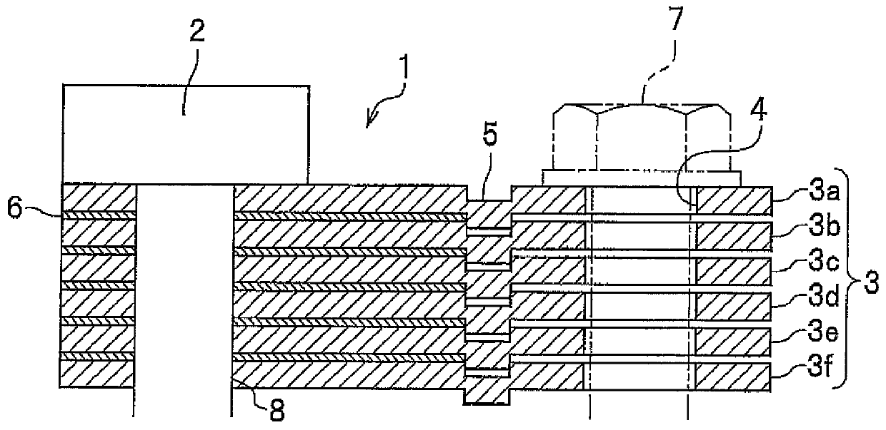
[0038] figure 1 The stator 1 consists of a stator core 3 and a slot 8 wound on the inside of the stator core 3 (refer to figure 2 ) On the stator coil 2. In addition, the stator 1 is bolted to a housing (not shown) of the rotating electric machine with a predetermined axial force through a fastening hole 4 provided in the outer peripheral portion of the stator core 3.

[0039] In addition, a rotor (not shown) of the rotating electric machine is inserted inside the stator 1.

[0040] The stator core 3 is formed by laminating plate-sha...


PUM


Abstract

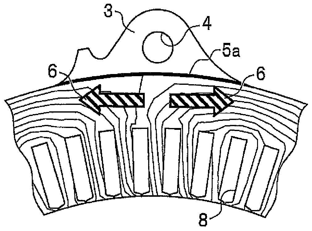
The invention provides a stator and a rotary motor comprising the same. The fastening force of the stator will not decrease due to the fatigue of a varnish. The provided stator (1) comprises a stator coil (2) and a stator iron core, which is formed by laminating electromagnetic steel plates. The stator iron core comprises a slot (8) for passing through the stator coil, a varnish arranged between the stator coil and the slot, and a fastening hole (4), which is arranged on the periphery of the stator iron core and is used to fasten the stator and a shell. A riveting part (5) is arranged between the fastening hole of the electromagnetic steel plates of the stator iron core and the slot; and the riveting part fixedly connects the electromagnetic steel plates and prevents the leakage of the varnish to the surrounding of the fastening hole. Specifically, the pivoting part fastens the laminated steel plates and makes the varnish to disperse along the ends of the steel plates in the periphery of the fastening part; or the pivoting part has a linear, hill shaped or arc shaped draw-bore pin between the fastening hole and the slot, and the draw-bore pin extends to the edges of the steel plates.

Description

Technical field [0001] The present invention relates to a stator of a rotating electric machine and a rotating electric machine equipped with the stator. Background technique [0002] In the stator of a rotating electric machine, as the surface treatment of the stator coil wound on the stator core on which electromagnetic steel sheets are laminated, a varnish is applied in order to strengthen the winding part and maintain insulation. Sometimes the varnish applied on the surface of the stator coil penetrates between the windings of the stator coil, and penetrates between the laminated electromagnetic steel sheets from the slots of the stator core. [0003] The stator is bolted to the housing of the rotating electric machine with a predetermined tightening force through a tightening portion provided on the periphery of the stator core. [0004] In general, the varnish applied to the stator coil causes insulation deterioration or "fatigue" (deformation) due to changes over the years. ...

Claims


Application Information

Patent Timeline
Patent Type & Authority Applications(China)
IPC IPC(8): H02K1/17
CPCH02K1/17
Inventor 朝日笃
Owner HONDA MOTOR CO LTD
Learn More