Lamp post system adopting groove mounting structure

A technology for installation structures and light poles, which is applied to the parts of lighting devices, lighting devices, fixed lighting devices, etc., can solve the problems of limited number of functional parts installed, low reliability, inconvenient installation, etc., to improve the stability of the connection and reliability, improve the ease of assembly, and facilitate the effect of installation and positioning

Pending Publication Date: 2020-10-30
HUNAN GOLDWELL NEW MATERIALS TECH CO LTD +1
View PDF0 Cites 0 Cited by
  • Summary
  • Abstract
  • Description
  • Claims
  • Application Information

AI Technical Summary

Problems solved by technology

[0003] At present, the functional parts are mainly installed on the light pole by means of hoops or direct screw fastening. Among them, the hoop installation method has the disadvantages of ugly appearance, high cost, and inconvenient installation, and because the hoop itself is easy to loosen and rotation, the fasteners connecting the hoop are also prone to rust and failure due to most of them being exposed, with poor stability and low reliability
The screw fastening installation method needs to set screw holes because the screws directly penetrate into the light pole, which will cause the light pole to rust easily and reduce the strength. At the same time, after installation, the connection position of the fastener is fixed and cannot be adjusted. In addition, limited by the structural space and strength of the light pole itself, the direct fastening method of fasteners also limits the number of functional parts installed.

Method used


Image

  • Lamp post system adopting groove mounting structure
  • Lamp post system adopting groove mounting structure
  • Lamp post system adopting groove mounting structure

Examples


Embodiment 1

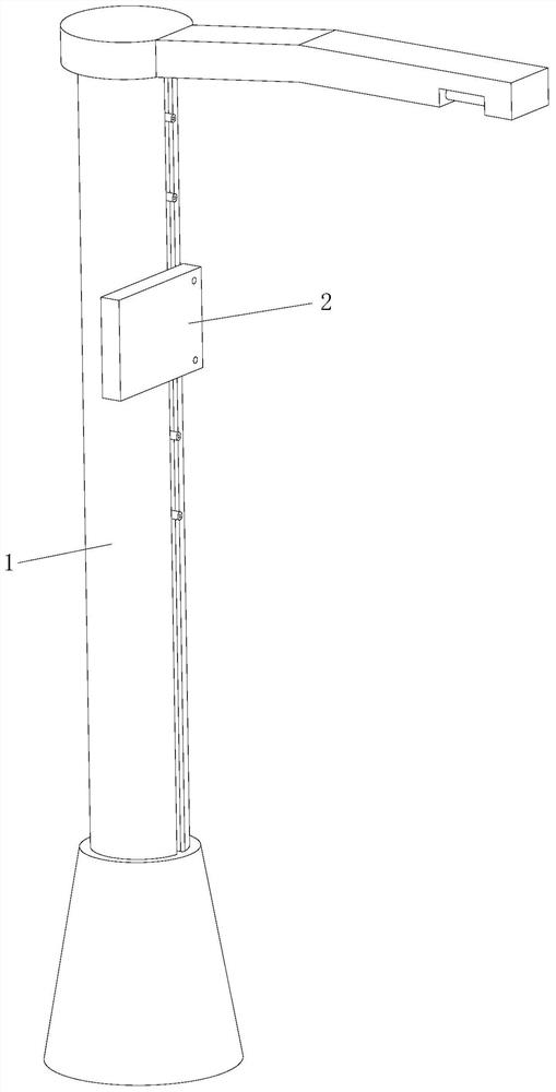
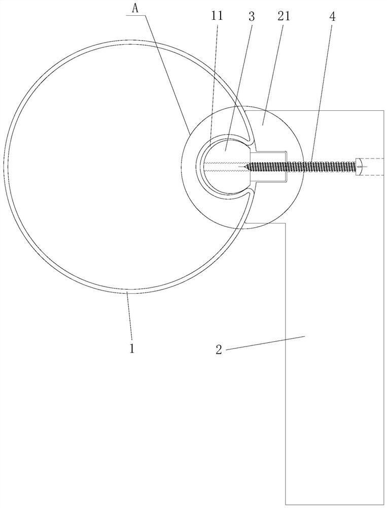
[0034] like figure 1 and figure 2 As shown, the light pole system adopting the groove installation structure in this embodiment includes a light pole main body 1 and more than one functional part 2. The light pole main body 1 has a installation groove extending along the length direction, and each installation groove corresponds to Each functional part 2 is detachably installed with a connecting part 3, and the functional part 2 is connected to the corresponding connecting part 3 through a detachable connecting mechanism. The light pole system adopts the main body 1 of the light pole with a mounting groove, and the connecting part 3 connected with the functional part 2 is detachably installed in the mounting groove. Compared with the traditional installation method, the connecting part 3 is hidden in the mounting groove In the middle, the aesthetics can be improved, and the matching structure of the connecting piece 3 placed in the installation groove can play a certain posi...

Embodiment 2

[0043] The light pole system using the groove installation structure of this embodiment is basically the same as that of Embodiment 1, the main difference is that, as Figure 4 and Figure 5 As shown, in the present embodiment, the cross-sections of the bottom groove bottom and the top groove body of the inner expansion groove 11 are rectangular, and the connector 3 can be inserted into the inner expansion groove 11 from the inner expansion groove 11 notch and can be inserted into the inner expansion groove 11. The expansion member positioned between the inner walls on both sides of the inner expansion groove 11 is tightened by rotation. The tensioning member of this embodiment can be a strip, and it is preferable to arrange a tensioning curved surface at both ends of the strip to realize gradual expansion. Specifically, the tensioning member can be a boat nut in the prior art.

[0044] In this embodiment, the connector 3 can be inserted into the inner expansion groove 11 fro...

Embodiment 3

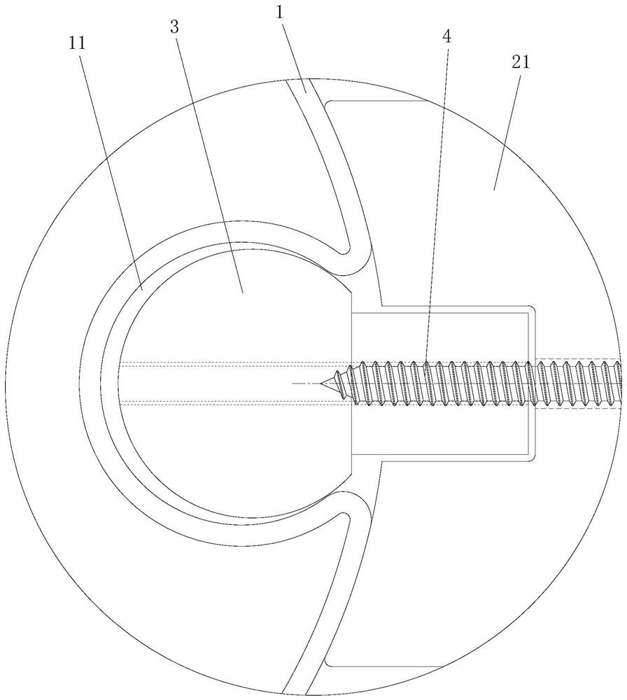
[0046] The light pole system based on the groove installation structure of this embodiment is basically the same as that of Embodiment 2, the main difference is that, as Image 6 and Figure 7 As shown, in this embodiment, the internal expansion groove 11 is a dovetail groove as a whole.


PUM


Abstract

The invention discloses a lamp post system adopting a groove mounting structure. The lamp post system comprises a lamp post body and one or more functional parts, the lamp post body is provided with an installation groove extending in the length direction, connecting parts corresponding to the functional parts are detachably installed in the installation groove, and the functional parts are connected with the corresponding connecting parts through detachable connecting mechanisms. The system has the advantages of simple and compact structure, low cost, simplicity and convenience in assembly, convenience in adjustment, good attractiveness, good connecting stability and reliability and the like.

Description

technical field [0001] The invention relates to the technical field of street lamps, in particular to a lamp pole system adopting a groove installation structure. Background technique [0002] The role of traditional light poles is relatively single, mainly used as a support for road lighting. With the needs of urban development and planning, more and more functional components are required to be installed on light poles, such as video surveillance equipment, WiFi hotspot equipment, communication base stations, environmental testing equipment, etc. [0003] At present, the functional parts are mainly installed on the light pole by means of hoops or direct screw fastening. Among them, the hoop installation method has the disadvantages of ugly appearance, high cost, and inconvenient installation, and because the hoop itself is easy to loosen And rotation, the fasteners connecting the hoop are also prone to rust and failure because most of them are exposed, with poor stability...

Claims


Application Information

Patent Timeline
Patent Type & Authority Applications(China)
IPC IPC(8): F21S8/08F21V21/10F21V17/10F21V21/34F21W131/103
CPCF21S8/086F21V17/10F21V21/10F21V21/34F21W2131/103
Inventor 谢斌泉其他发明人请求不公开姓名
Owner HUNAN GOLDWELL NEW MATERIALS TECH CO LTD
Why Eureka
Try Eureka