
Electrode, power storage device, and electronic equipment

a technology of power storage device and electrode, which is applied in the direction of wound/folded electrode electrode, sustainable manufacturing/processing, cell components, etc., can solve the problems of the tendency of the capacity and cycle characteristics of the secondary batteries to deteriorate, and achieve the effect of reducing the friction force acting on the contact surface when the surface of the electrode and another component comes in contact with each other, preventing the damage of the electrode, and reducing the stress caused by the difference between the inner diameter and the outer diameter curv

Active Publication Date: 2020-09-08
SEMICON ENERGY LAB CO LTD
View PDF47 Cites 0 Cited by
  • Summary
  • Abstract
  • Description
  • Claims
  • Application Information

AI Technical Summary

Benefits of technology

[0010]An object of one embodiment of the present invention is to provide a power storage device having flexibility. Another object of one embodiment of the present invention is to provide a power storage device of which the capacity and cycle characteristics are not likely to deteriorate even when the power storage device is curved or bent. Another object of on embodiment of the present invention is to provide electronic equipment with a flexible power storage device.
[0030]Any of the above power storage devices may have flexibility.
[0032]According to one embodiment of the present invention, the electrodes in the power storage device can be protected. According to one embodiment of the present invention, damage to the electrodes can be prevented. According to one embodiment of the present invention, friction force acting on the contact surface when the surface of the electrode and another component come in contact with each other can be decreased. According to one embodiment of the present invention, friction force acting on the contact surface when two electrodes, the electrode and the separator, or the electrode and the exterior body come in contact with each other along with curving of a flexible power storage device is decreased, whereby stress caused by the difference between the inner diameter and outer diameter of the curve can easily be relieved. Thus, damage to the electrode, which is caused by a locally steep curve of the electrode when curving a power storage device, can be prevented. Furthermore, the electrode can be prevented from having a portion with a locally steep curve and a portion being hardly curved, when curving a power storage device. Moreover, variations in distance between the positive electrode and the negative electrode can be reduced. Furthermore, decrease in capacity or deterioration of a power storage device due to curving can be suppressed.

Problems solved by technology

When such secondary batteries are curved or bent, the capacity and cycle characteristics of the secondary batteries tend to deteriorate.

Method used


Image

  • Electrode, power storage device, and electronic equipment
  • Electrode, power storage device, and electronic equipment
  • Electrode, power storage device, and electronic equipment

Examples


embodiment 1

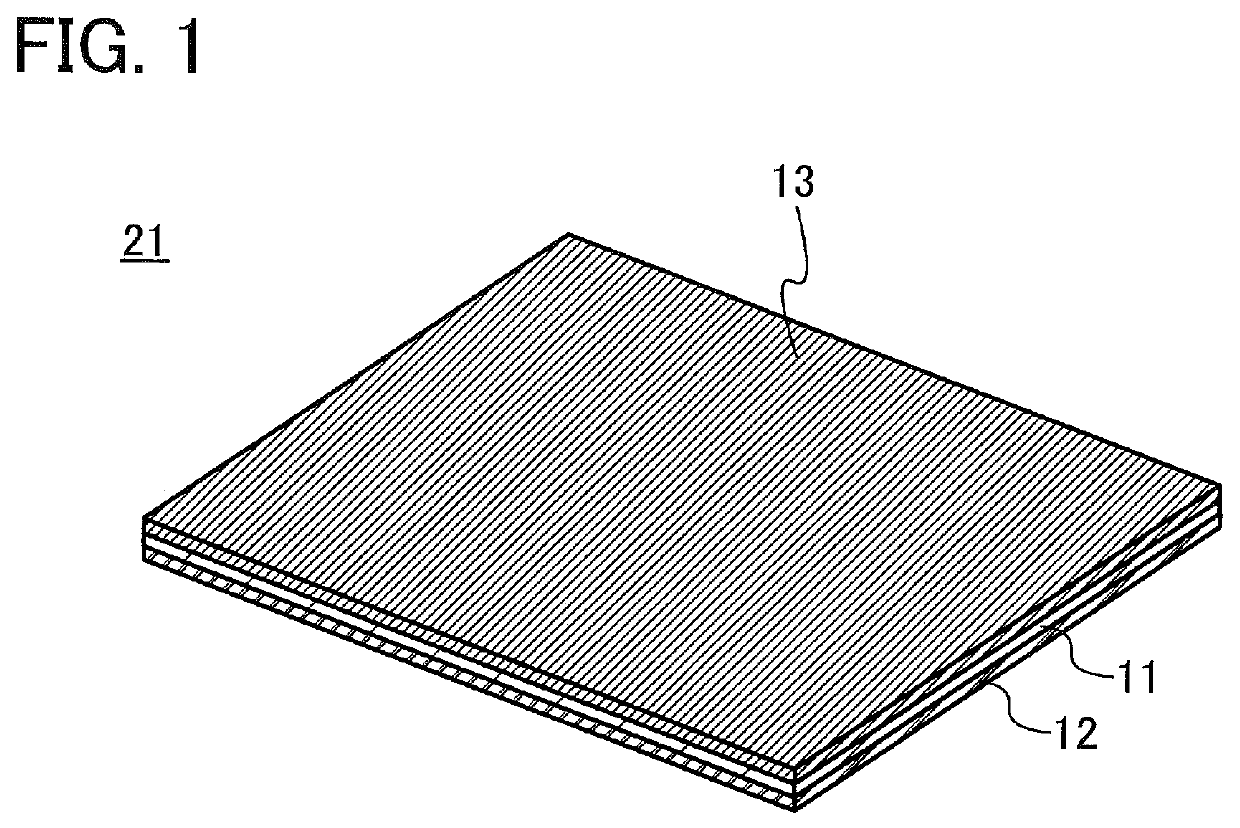
[0067]In this embodiment, the structure of an electrode of one embodiment of the present invention will be described with reference to FIG. 1.

[0068]An electrode 21 shown in FIG. 1 includes a sheet-like current collector 11, an active material layer 12 on one side of the current collector 11, and a friction layer 13 in contact with the other side of the current collector 11.

[0069]It is preferable that friction force acting on the contact surface between the surface of the friction layer 13 and a surface in contact with the friction layer 13 be smaller than friction force acting on the contact surface between the surface of the current collector 11 and a surface in contact with the current collector 11. Specifically, the coefficient of static friction between the friction layer 13 and the surface in contact with the friction layer 13 is preferably less than or equal to 0.6, more preferably less than or equal to 0.2, and even more preferably less than or equal to 0.05.

[0070]The current...

embodiment 2

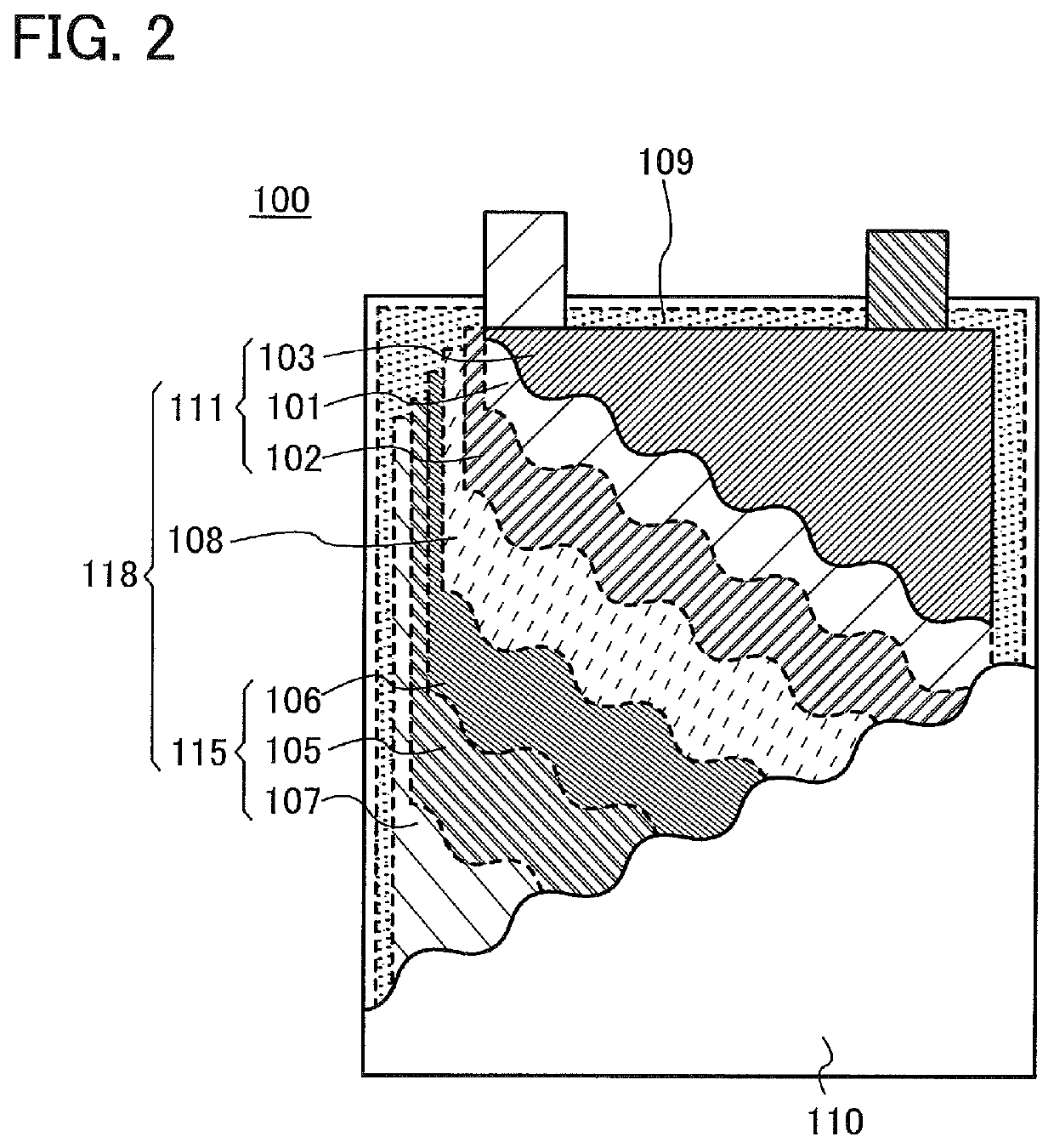
[0126]In this embodiment, the structure of a secondary battery of one embodiment of the present invention will be described with reference to FIG. 2.

[0127]FIG. 2 illustrates a laminate-type secondary battery 100 in which a stack 118 including a positive electrode 111, a negative electrode 115, and a separator 108 is sealed in a flexible exterior body 110 to which an electrolytic solution 109 is injected. When a secondary battery is of a laminate-type, the battery has flexibility and thus is suitable for applications that require flexibility. For example, when a flexible secondary battery is used in electronic equipment at least part of which is flexible, the secondary battery can be curved as the electronic equipment is curved.

[0128]In FIG. 2, each of the positive electrode 111 and the negative electrode 115 is the electrode described in Embodiment 1. The positive electrode 111 includes a positive electrode active material layer 102 on one side of a positive electrode current collec...

embodiment 3

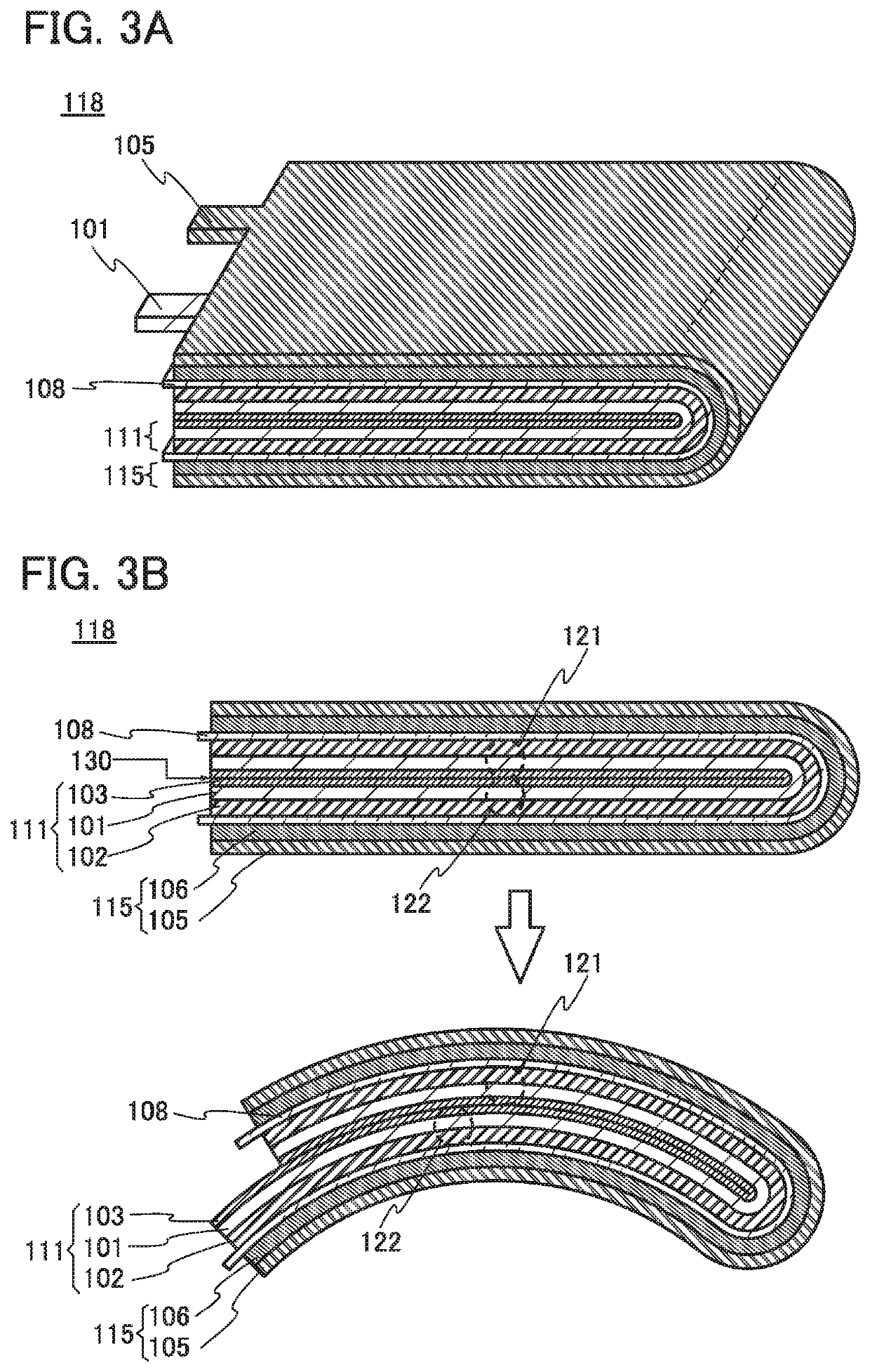
[0149]In this embodiment, a power storage device of one embodiment of the present invention will be described with an example of the secondary battery, with reference to FIGS. 3A and 3B, FIGS. 4A to 4C, FIG. 5, FIGS. 6A to 6C, FIGS. 7A and 7B, FIGS. 8A and 8B, FIGS. 9A and 9B, FIG. 10, FIGS. 11A and 11B, and FIG. 12.

[0150]As described in Embodiment 2, the secondary battery 100 includes the stack 118 including the positive electrode 111, the negative electrode 115, and the separator 108; the exterior body; and the electrolytic solution. In this embodiment, examples of the structure of the stack 118 will be described.

[0151]For the description of the positive electrode 111 and the negative electrode 115 in this embodiment, Embodiment 1 can be referred to. For the description of the separator 108 and the electrolytic solution 109, Embodiment 2 can be referred to.

[0152]Note that in this embodiment, the positive electrode 111 and the negative electrode 115 may be interchanged with each ot...


PUM

PropertyMeasurementUnit
arithmetic average roughnessaaaaaaaaaa
thicknessaaaaaaaaaa

Abstract

A flexible power storage device or a power storage device of which the capacity and cycle characteristics do not easily deteriorate even when the power storage device is curved is provided. An electrode in which an active material layer, a current collector, and a friction layer are stacked in this order is provided. Furthermore, a power storage device that includes the electrode as at least one of a positive electrode and a negative electrode is provided.

Description

BACKGROUND OF THE INVENTION[0001]1. Field of the Invention[0002]One embodiment of the present invention relates to an electrode, a power storage device, and electronic equipment.[0003]Note that one embodiment of the present invention is not limited to the above technical field. One embodiment of the invention disclosed in this specification and the like relates to an object, a method, or a manufacturing method. One embodiment of the present invention relates to a process, a machine, manufacture, or a composition of matter. Specifically, examples of the technical field of one embodiment of the present invention disclosed in this specification include a semiconductor device, a display device, a light-emitting device, a power storage device, a memory device, a method for driving any of them, and a method for manufacturing any of them.[0004]Note that electronic equipment in this specification generally means devices driven by electricity; and electro-optical devices, information termina...

Claims


Application Information

Patent Timeline
Patent Type & Authority Patents(United States)
IPC IPC(8): H01M2/02H01M4/62H01M10/04H01M4/13H01M4/02H01M10/0583H01M50/105
CPCH01M4/62H01M4/13H01M10/0431H01M2/02Y02E60/10Y02P70/50H01M50/105
Inventor TAJIMA, RYOTAMOMO, JUNPEIYAMAKAJI, MASAKI
Owner SEMICON ENERGY LAB CO LTD
Learn More