Glue gun

a glue gun and glue technology, applied in the direction of liquid surface applicators, coatings, etc., can solve the problems of difficult to keep glue sticks in the gun entry port, the gun uses only one glue stick at a time, and interruption can be disadvantageous

Active Publication Date: 2020-12-08
HORIAN RICHARD C
View PDF17 Cites 9 Cited by
  • Summary
  • Abstract
  • Description
  • Claims
  • Application Information

AI Technical Summary

Benefits of technology

[0005]The present invention is directed to a charging cylinder for a hot melt glue gun for continuously advancing hot melt glue without having to reload the glue gun. The charging cylinder includes a shaft extending rearwardly from the glue gun rotatably mounting a cylinder having a plurality of chambers parallel to the shaft and equidistantly spaced from the shaft. The chambers can be selectively aligned with the gun to feed hot melt glue sticks into the gun. Elements may additionally be used to bias retention of the hot melt glue sticks toward the gun.

Problems solved by technology

One inconvenience is that the guns use only one glue stick at a time.
This interruption can be disadvantageous in the gluing operation.
Another problem working with conventional hot melt glue guns is that the glue sticks are hard to keep in the gun entry port before being secured by the trigger gripper.

Method used


Image

  • Glue gun
  • Glue gun
  • Glue gun

Examples


Embodiment Construction

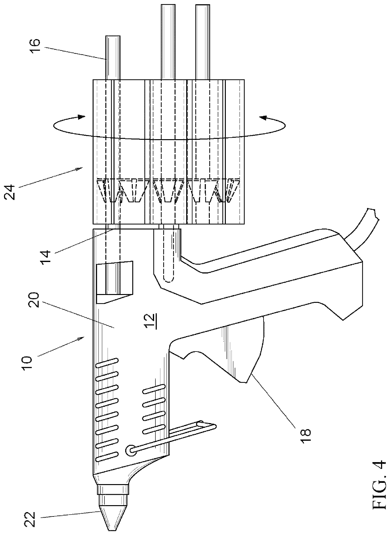
[0012]Turning in detail to the drawings, the basic design of electric glue guns 10 need not be changed from its current popular configuration consisting of a pistol shaped housing 12 including an open glue stick entry port 14 at the rear of the gun 10 that will accept a solidified glue stick 16 made of glue that is solid at room temperature. The glue stick 16 is pushed forward until it engages rubber like grippers controlled by a trigger mechanism 18 located under the housing of the glue gun 10. The glue gun 10 is then operated by squeezing the trigger 18 beneath the body of the gun 10. The trigger 18 is squeezed to advance the glue stick 16 forward into the melt zone through a barrel 20. Each squeeze of the trigger 18 will force molten liquefied glue out of the front nozzle 22 until the glue stick 16 is depleted.

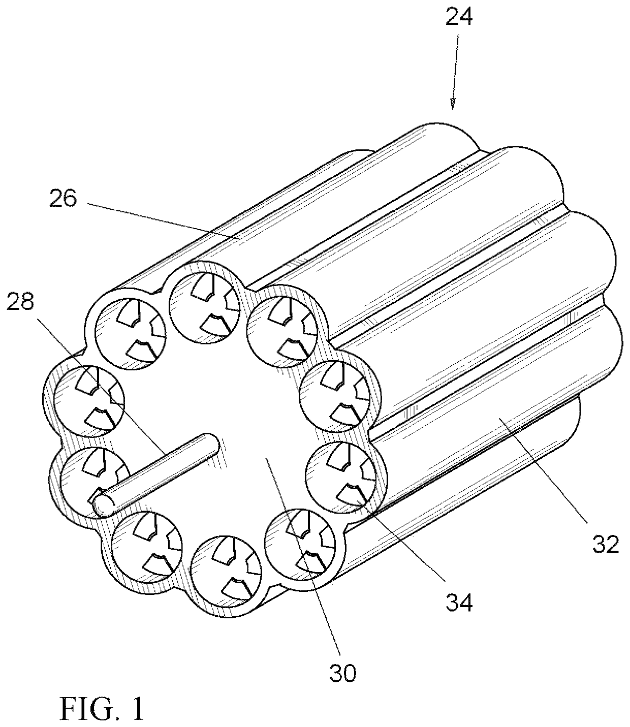
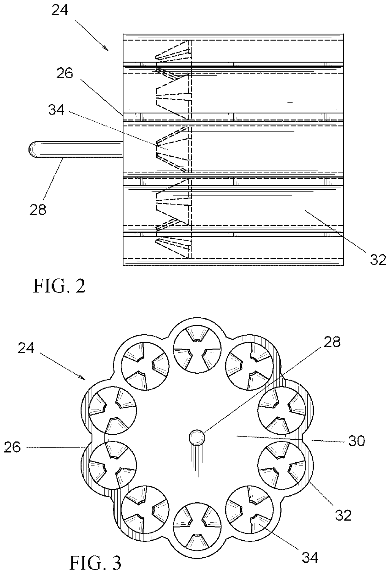
[0013]A charging cylinder 24 is mounted at the back of the gun housing 12. A cylinder 26 in the preferred embodiment takes a cylindrical shape with its center line position...


PUM


Abstract

A hot melt glue gun includes a charging cylinder mounted to the rear of the gun with chambers for holding solid glue sticks. The cylinder is mounted to the hot melt gun housing via a centered shaft allowing it to revolve circumferentially. The cylinder is mounted in a position on the back of the glue gun so that each chamber when rotated to the top aligns with the glue stick entry port in the back of the glue gun. Each chamber has resilient flanges within the chamber that cause friction when a glue stick is inserted into the chamber, thus lightly securing the glue stick before it is pushed forward into the glue gun port and taken up by the trigger activated forward grip.

Description

BACKGROUND OF THE INVENTION[0001]The field of the present invention is hot melt glue guns.[0002]Electric glue guns use a rod shaped adhesive formed as a glue stick that is solid at room temperature and then melts when a heating element positioned inside the gun liquefies the adhesive as the hot melt glue stick progresses past the heating element and leaves the gun in liquid form via a nozzle at the front of the gun. The solid hot melt glue stick first enters the glue gun through a glue stick entry port at the rear of the gun aligned with a barrel extending to the nozzle. The glue stick then enters friction grippers that secure the glue stick. A trigger located at the underside of the gun progresses the grippers to move the glue stick forward with each squeeze of the trigger. The glue stick melts as it passes through the melt zone and is forced out of the front nozzle of the gun as the next squeeze of the trigger forces the glue stick further forward to melt and progress the molten g...

Claims


Application Information

Patent Timeline
Patent Type & Authority Patents(United States)
IPC IPC(8): B05C17/005B05C17/00
CPCB05C17/0053B05C17/002B05C17/0052B05C17/001B05C17/00526
Inventor HORIAN, RICHARD C.
Owner HORIAN RICHARD C
Why Eureka
Try Eureka