
Vacuum pressure regulators for use during blood collection

a vacuum pressure regulator and blood collection technology, applied in the field of vacuum pressure regulators for use during blood collection, can solve the problems of restricting the flow path within the fluid passageway, and achieve the effects of avoiding the initial pressure spike, slowing down the initial flow rate of blood, and reducing the collapse of the vessel

Active Publication Date: 2021-01-12
BECTON DICKINSON & CO
View PDF28 Cites 0 Cited by
  • Summary
  • Abstract
  • Description
  • Claims
  • Application Information

AI Technical Summary

Benefits of technology

[0010]The vacuum pressure regulator of the present invention minimizes vessel collapse by controlling the flow rate out of the patient's blood vessel. The present invention slows down the initial flow rate of blood into an evacuated tube to avoid the initial pressure spike.
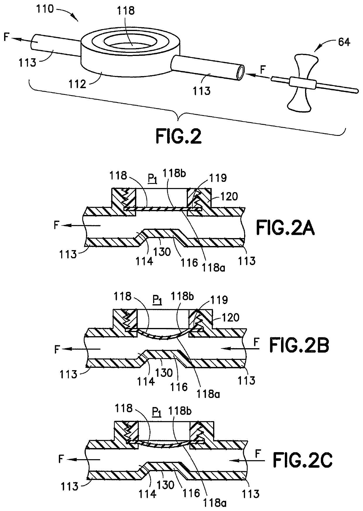
[0019]A thumb pad can be associated with the flexible member to enable a user to over-ride the automatic regulation of blood flow and to manually regulate the flow of blood through the blood flow passageway.
[0024]The method can also include associating a thumb pad with the flexible member to enable a user to over-ride the automatic regulation of blood flow and to manually regulate the flow of blood through the blood flow passageway.

Problems solved by technology

Exposure of the fluid passageway to the vacuum creates a pressure gradient across the flexible member causing at least a portion of the flexible member to extend into the fluid passageway resulting in a restricted flow path within the fluid passageway.

Method used


Image

  • Vacuum pressure regulators for use during blood collection
  • Vacuum pressure regulators for use during blood collection
  • Vacuum pressure regulators for use during blood collection

Examples


Embodiment Construction

[0040]For purposes of the description hereinafter, the terms “upper”, “lower”, “right”, “left”, “vertical”, “horizontal”, “top”, “bottom”, “lateral”, “longitudinal”, and derivatives thereof, shall relate to the invention as it is oriented in the drawing figures. However, it is to be understood that the invention may assume various alternative variations, except where expressly specified to the contrary. It is also to be understood that the specific devices illustrated in the attached drawings, and described in the following specification, are simply exemplary embodiments of the invention. Hence, specific dimensions and other physical characteristics related to the embodiments disclosed herein are not to be considered as limiting.

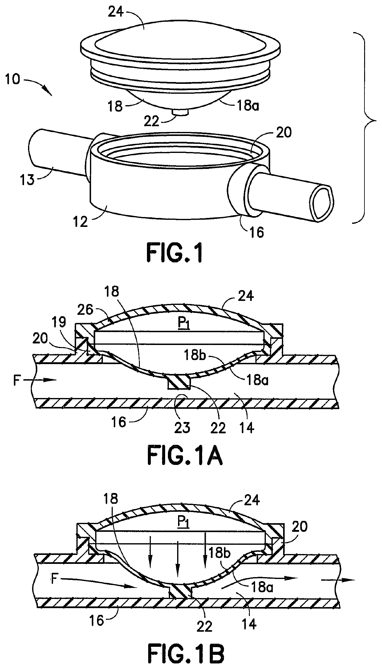
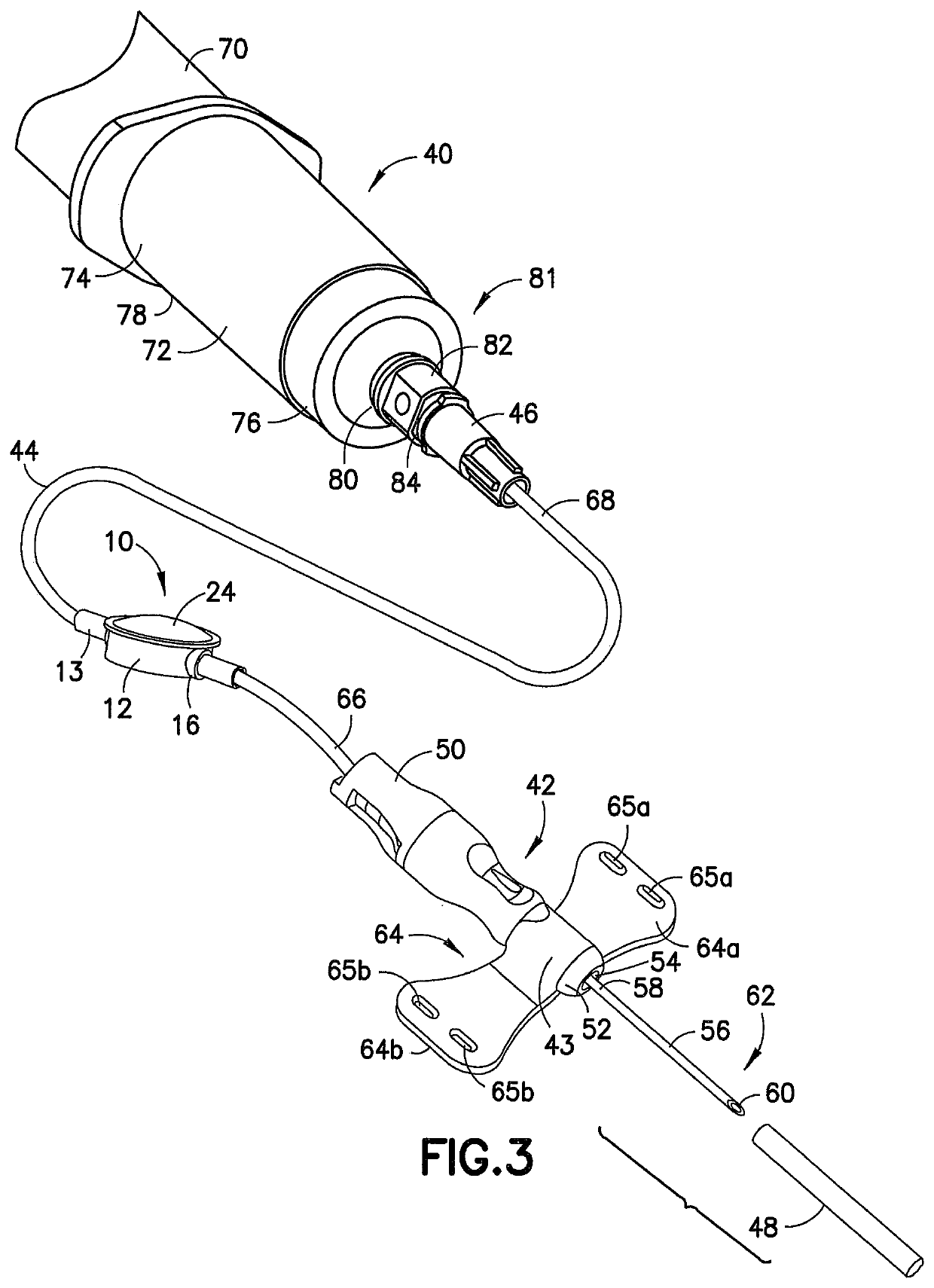
[0041]Reference is now made to FIGS. 1, 1A, and 1B, which show a pressure regulator, generally indicated as 10, for flow modulation during fluid collection to prevent the collapse of a patient's blood vessel. The regulator 10 includes a fluid transfer device...


PUM


Abstract

A regulator for in-line modulation of the flow rate of fluid during blood collection includes a fluid transfer device for transferring fluid from a patient to a collection device. The fluid transfer device comprises a fluid passageway defined by a tubular sidewall and a flexible member associated with a portion of the tubular sidewall. The flexible member is configured for movement with respect to the fluid passageway upon exposure of the fluid transfer device to a differential pressure during a blood collection procedure to prevent collapse of a patients blood vessel. The flexible member of the regulator can be a frame surrounding a flexible diaphragm. Alternatively, the flexible member can include a flexible material integrally formed within the tubular sidewall of the pressure regulator.

Description

CROSS-REFERENCE TO RELATED APPLICATIONS[0001]This application is the United States national phase of International Application No. PCT / US2013 / 041181 filed May 15, 2013 the disclosure of which is hereby incorporated in its entirety by reference.BACKGROUND OF THE INVENTION[0002]Field of the Invention[0003]The present invention relates to a regulator for flow modulation to prevent the collapse of a patient's blood vessel during blood collection and, more particularly, to a variable flow resistor that acts to slow down the initial flow rate of blood into an evacuated blood collection device. The present invention also minimizes the initial spike in flow rate caused by vacuum pressure and slows down the overall blood collection time to avoid rapid depletion of resident blood within the vessel.[0004]Description of Related Art[0005]Phlebotomy procedures are often carried out using a blood collection device or intravenous (IV) infusion device. A typical blood collection or (IV) infusion dev...

Claims


Application Information

Patent Timeline
Patent Type & Authority Patents(United States)
IPC IPC(8): A61B5/15G05D7/01A61B5/154A61M5/168A61B5/153A61M39/24
CPCA61B5/150946A61B5/153A61B5/15003A61B5/154A61B5/15074A61B5/150221A61B5/150389A61B5/150503A61B5/150572A61B5/150587A61B5/150717A61B5/150992A61M5/16813A61M5/16881G05D7/0113A61M2039/246A61M2039/2433
Inventor RUSS, CRAIG OWENCHIA, NEVILLE YU LENGCRAWFORD, JAMIESON W.SMITH, KENNETH JAMESWILKINSON, BRADLEY M.
Owner BECTON DICKINSON & CO
Learn More