
Integrated system for generating, storing and dispensing clean energy and desalinating water

a technology of clean energy and desalination water, which is applied in the direction of quarries' waste water treatment, membranes, greenhouse gas reduction, etc., can solve the problems of reducing achieve the reduction of energy inputs and consequently air emissions, reduce the net cost of clean energy storage, and reduce the pumping of the ro desalination process

Active Publication Date: 2021-02-16
OCEANUS POWER & WATER LLC
View PDF15 Cites 0 Cited by
  • Summary
  • Abstract
  • Description
  • Claims
  • Application Information

AI Technical Summary

Benefits of technology

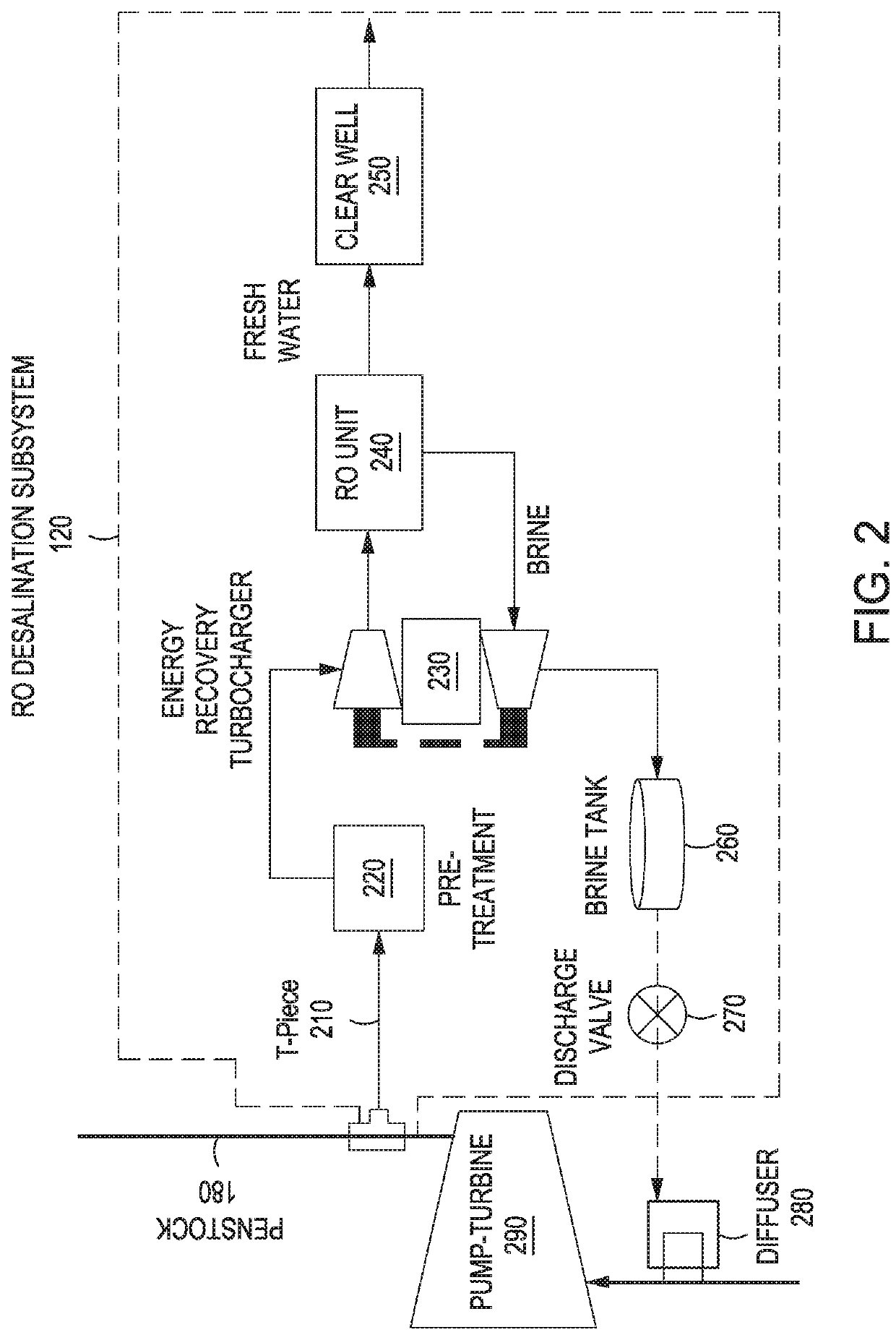
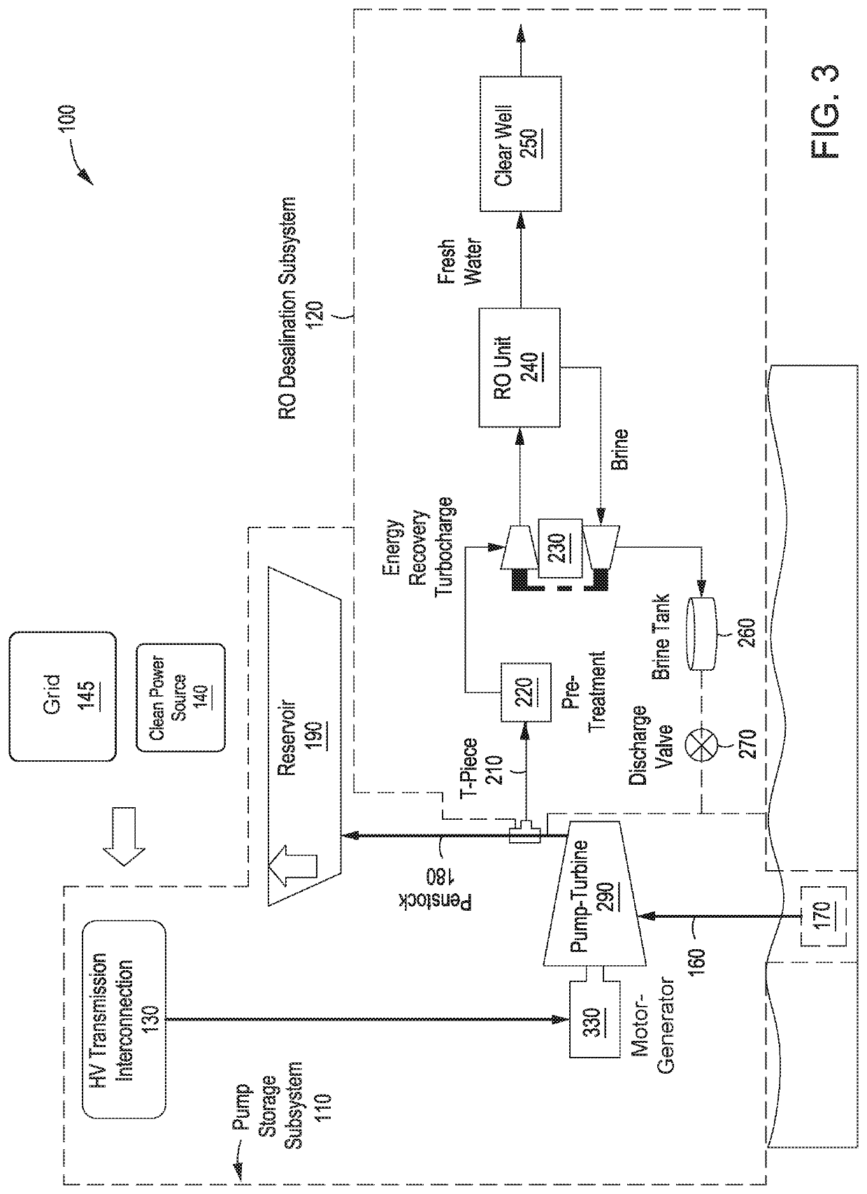
[0011]One advantage of the disclosed techniques is that the integrated system reduces the net cost of clean energy storage and seawater desalination in multiple ways. In terms of capital costs, the integrated system utilizes shared inflow-outflow structures, electrical grid connections, pipelines, and ancillary buildings, reduced pumps in the RO desalination process. In terms of operating costs, the integrated system reduces the energy inputs and consequently air emissions for the RO desalination subsystem. In addition, the environmental performance of these systems is improved by storing intermittently generated clean energy which may otherwise be curtailed or stored by other much more expensive means, and deploying stored hydraulic energy to drive the RO desalination subsystem.
[0012]Further advantages may also include mitigating the environmental impacts of the RO desalination process by diluting brine from the RO desalination subsystem with water being utilized for hydraulic energy production. Moreover, design risks are reduced by utilizing proven systems, including hydroelectric pump-turbines, motor-generators, penstocks, RO membranes, energy recovery devices, turbochargers, high pressure filtration equipment, and reservoirs, and solar and wind generation plants.

Problems solved by technology

In terms of operating costs, the integrated system reduces the energy inputs and consequently air emissions for the RO desalination subsystem.

Method used


Image

  • Integrated system for generating, storing and dispensing clean energy and desalinating water
  • Integrated system for generating, storing and dispensing clean energy and desalinating water
  • Integrated system for generating, storing and dispensing clean energy and desalinating water

Examples


Embodiment Construction

[0019]In the following description, numerous specific details are set forth to provide a more thorough understanding of the present invention. However, it will be apparent to one of skill in the art that the present invention may be practiced without one or more of these specific details.

System Overview

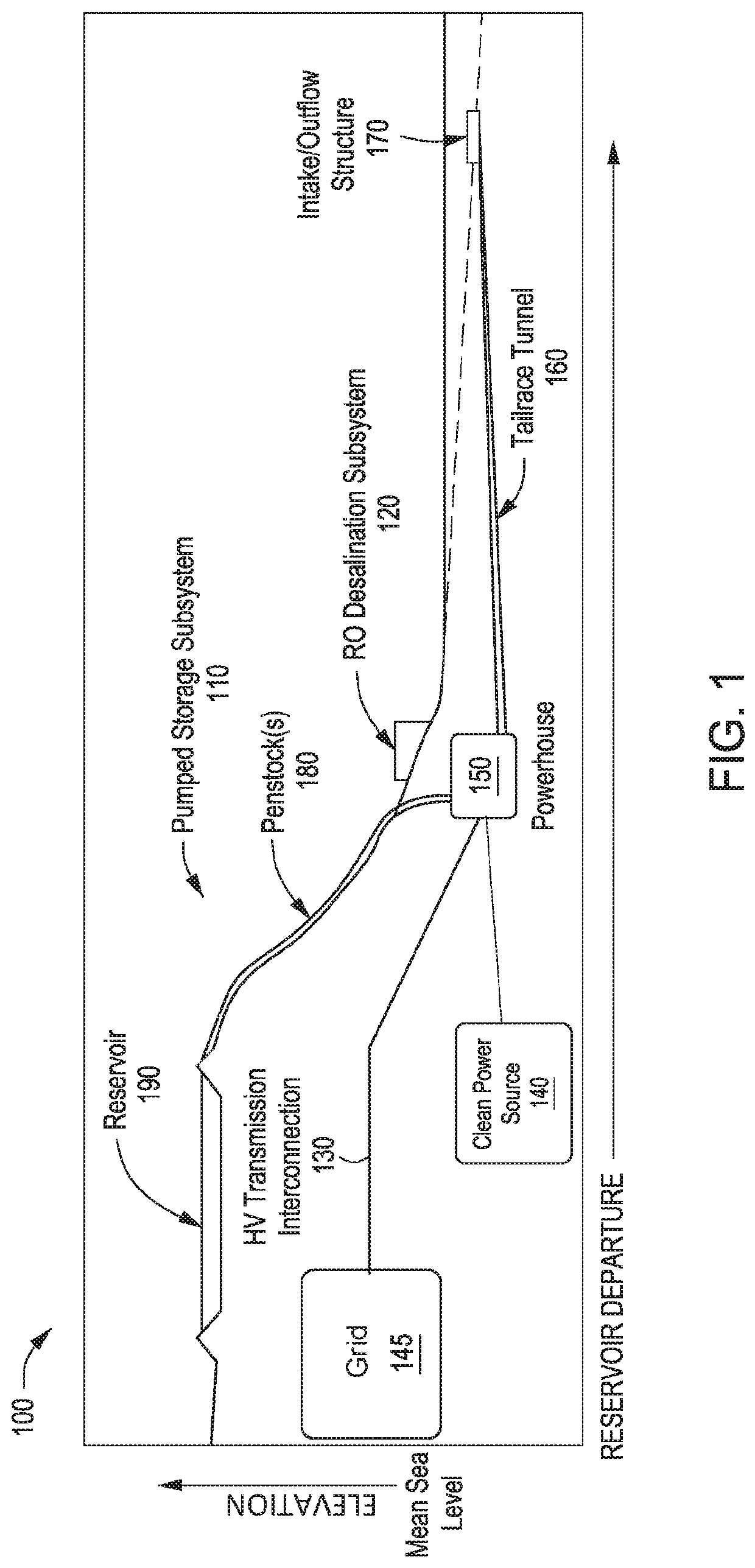
[0020]FIG. 1 is a conceptual illustration of an integrated system 100 configured to implement one or more aspects of the present invention. As shown, integrated system 100 includes, without limitation, high voltage transmission interconnections 130, a clean power source 140, a powerhouse 150, a tailrace tunnel 160, a seawater intake / outflow structure 170, a RO desalination subsystem 120, a penstock(s) 180, and a reservoir 190. For explanatory purposes, multiple instances of like objects are denoted with reference numbers identifying the object and parenthetical numbers identifying the instance where needed.

Pumped Storage Subsystem

[0021]In various embodiments, the power supply for the ...


PUM

PropertyMeasurementUnit
pressureaaaaaaaaaa
pressureaaaaaaaaaa
pressureaaaaaaaaaa

Abstract

Embodiments of this invention provide an integrated system for clean energy generation and storage and RO desalination. The integrated system includes a first subsystem that stores hydraulic energy. The integrated system further includes a second subsystem that desalinates water. The integration system also includes a penstock that facilitates flow of the water between the first subsystem and the second subsystem. The integrated subsystem may also incorporate solar and / or wind power generation plants as a power source for the integrated system.

Description

CROSS-REFERENCE TO RELATED APPLICATIONS[0001]This application claims benefit of United States Provisional Patent Application titled, “System Integrating Renewable Energy, Salt Water Pumped Hydroelectric Storage, and Reverse Osmosis Desalination,” filed Apr. 10, 2017 and having Ser. No. 62 / 483,879, and claims benefit of United States Provisional Patent Application titled, “System Integrating Renewable Energy, Pumped Hydroelectric Storage, and Reverse Osmosis Desalination for Mine Development and Operations,” filed Jun. 1, 2017 and having Ser. No. 62 / 513,845. The subject matter of these related applications are hereby incorporated herein by reference.BACKGROUND OF THE INVENTIONField of the Invention[0002]Embodiments of the present invention relate generally to renewable energy and water desalination, and specifically, to an integrated system for generating, storing and dispensing clean energy and desalinating water.Description of the Related Art[0003]Many systems exist that enable the...

Claims


Application Information

Patent Timeline
Patent Type & Authority Patents(United States)
IPC IPC(8): C02F1/44C02F1/00B01D61/02B01D61/06B01D61/08B01D61/10C02F103/10C02F1/32C02F1/66C02F103/08
CPCC02F1/441B01D61/025B01D61/06B01D61/08B01D61/10C02F1/004B01D2311/04B01D2313/246B01D2313/36B01D2313/365C02F1/32C02F1/66C02F2103/08C02F2103/10C02F2201/009C02F2209/04C02F2303/04C02F2303/10Y02A20/131Y02A20/141Y02E10/20Y02E10/72Y02E60/16Y02W10/33Y02W10/37Y02A20/212Y02W10/30Y02A20/152Y02E70/30B01D2313/367B01D2311/2642B01D2311/2673
Inventor ARONSON, NEALWALKER, SANDRAGUERRERO, JOSE ALBERTO GARCIAJELDREZ, JOAN LEALALLEN, MARK
Owner OCEANUS POWER & WATER LLC
Learn More