Information handling system housing integrated vapor chamber

a technology of information handling system and vapor chamber, which is applied in the direction of portable computer details, instruments, climate sustainability, etc., can solve the problems of increasing the thickness of the system, and affecting the thermal management of the information handling system. , to achieve the effect of enhancing the passive transfer of thermal energy, and reducing the number of vapor chambers

Active Publication Date: 2021-04-06
DELL PROD LP
View PDF91 Cites 7 Cited by
  • Summary
  • Abstract
  • Description
  • Claims
  • Application Information

AI Technical Summary

Benefits of technology

[0015]Therefore, a need has arisen for a system and method which enhances passive transfer of thermal energy from a low profile information handling system housing.
[0020]In accordance with the present invention, a system and method are provided which substantially reduce the disadvantages and problems associated with previous methods and systems to passively transfer thermal energy from an information handling system housing. Thermal energy generated by power dissipation at a first housing portion, such as execution of instructions on a CPU, is transferred through a thermal conduit to a second rotationally coupled housing portion for rejection to an external environment. In various embodiments, the thermal conduit passes through one or more hinges rotationally coupling the housing portions to each other and has the amount of thermal energy that is transferred managed by altering thermal characteristics of thermal conduits and / or thermal dissipation devices integrated in the housing portions. For instance, one or more vapor chambers integrated in one or more housing portions alters an internal pressure to adapt a saturation point for fluid phase change, thus adjusting the efficiency of thermal transfer across the vapor chamber. Management of thermal transfer at housing portions provides a tool for maintaining housing portion outer surfaces and internal components within a temperature threshold.
[0022]The present invention provides a number of important technical advantages. One example of an important technical advantage is enhanced passive transfer of thermal energy from a low profile information handling system. Thermal energy rejects more efficiently from an information handling system with a greater surface area exposed to an external environment. Further, thermal energy rejects more efficiently from a vertically raised surface as thermal energy rises. Thus, transferring thermal energy to a lid housing portion improves passive thermal cooling as the lid housing portion generally doubles the surface area from which thermal energy is rejected and is raised in a vertical orientation to hold a display integrated in the lid housing portion in a viewing position.
[0023]Another example of an important technical advantage is dynamic control of passive thermal energy rejection to manage information handling system component and housing temperatures. For example, manipulating the pressure within a vapor chamber adjusts the saturation point of a fluid in the vapor chamber, thus adapting the efficiency with which thermal energy is dissipated across the vapor chamber. Active control of pressure in one or more vapor chambers manages temperatures at locations throughout an information handling system. For instance, if a lid housing portion outer surface reaches too high of a temperature, increasing the pressure within a vapor chamber of the lid housing portion decreases thermal energy transfer to lower the outer surface temperature. In one embodiment, pressure management is automated with a wax motor that melts to increase pressure when temperatures reach a defined threshold.
[0025]Another example of an important technical advantage is distribution of thermal energy between rotationally coupled housing portions independent of the hinges coupling the housing portions to each other. For example a graphite sheet or plural layers of graphite sheets provide excellent in plane thermal conduction to transfer thermal energy between housing portions. Graphite formed in the shape of a torsion spring interfaces between housing portions with minimal disruption of information handling system operation, such as by wrapping around a hinge pin or shaft, or routing through a slot defined by parallel bars that maintain a minimal bend radius to protect the thermal transfer material from cracking or breaking.

Problems solved by technology

Tablet information handling systems' relatively flat housings and minimal input device provide a thin and light weight system, however, interactions that involve end user inputs tend to be more time consuming in the absence of a keyboard input device.
One difficulty with convertible information handling system configurations is that rotationally coupling housing portions to each other tends to increase the thickness of the system.
Another difficulty with convertible information handling system configurations is that processing component power dissipation is limited by thermal constraints that include a maximum temperature associated with the each processing component and a maximum temperature of the housing surface.
In particular, CPU operation tends to dissipate power at a concentrated location that can result in excessive thermal conditions.
However, as CPU clock speed reduces, processing speeds also decrease, resulting in slower system response.
Active cooling systems tend to increase the size of a portable housing and also increase power consumption.
Typically, low profile information handling system housings lack room to support active cooling.
Instead, such systems tend to rely upon passive cooling to dissipate excess thermal energy.
In some instances, low profile housing passive thermal transfer may support higher transient CPU power consumption levels, however, extended operations at high power dissipations tends to eventually result in CPU throttling and decreased performance.

Method used


Image

  • Information handling system housing integrated vapor chamber
  • Information handling system housing integrated vapor chamber
  • Information handling system housing integrated vapor chamber

Examples


Embodiment Construction

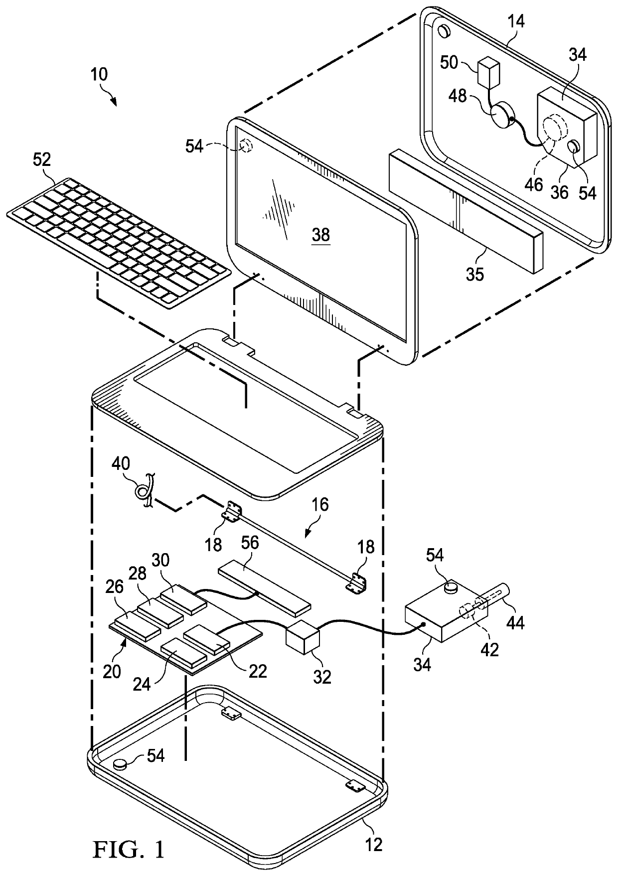
[0066]An information handling system transfers thermal energy between rotationally coupled housing portions to improve thermal dissipation and rejection. For purposes of this disclosure, an information handling system may include any instrumentality or aggregate of instrumentalities operable to compute, classify, process, transmit, receive, retrieve, originate, switch, store, display, manifest, detect, record, reproduce, handle, or utilize any form of information, intelligence, or data for business, scientific, control, or other purposes. For example, an information handling system may be a personal computer, a network storage device, or any other suitable device and may vary in size, shape, performance, functionality, and price. The information handling system may include random access memory (RAM), one or more processing resources such as a central processing unit (CPU) or hardware or software control logic, ROM, and / or other types of nonvolatile memory. Additional components of t...


PUM


Abstract

A portable information handling system transfers thermal energy associated with operation of processing components in a main housing portion to a vapor chamber integrated in a lid housing portion that distributes the thermal energy across the lid housing portion. A hinge protrusion formed in the lid housing portion defines a cylindrical opening that accepts a hinge pin to rotationally couple the housing portions to each other. The cylindrical wall defines a barrier with the vapor chamber so that a thermal conduit passing from the main housing portion to the hinge pin transfers thermal energy from the hinge pin through the cylindrical wall to the vapor chamber.

Description

CROSS REFERENCE TO RELATED APPLICATIONS[0001]U.S. patent application Ser. No. 15 / 952,519, filed Apr. 13, 2018, now U.S. Pat. No. 10,802,555, entitled “Information Handling System Thermally Conductive Hinge” by inventors Travis C. North, Mark A. Schwager, Austin M. Shelnutt, and John T. Morrison, describes exemplary methods and systems and is incorporated by reference in its entirety.[0002]U.S. patent application Ser. No. 15 / 952,528, filed Apr. 13, 2018, now U.S. Pat. No. 10,401,926, entitled “Information Handling System Housing Thermal Conduit Interfacing Rotationally Coupled Housing Portions” by inventors Travis C. North, Mark A. Schwager, Austin M. Shelnutt, and John T. Morrison, describes exemplary methods and systems and is incorporated by reference in its entirety.[0003]U.S. patent application Ser. No. 15 / 952,536, filed Apr. 13, 2018, entitled “Information Handling System Dynamic Thermal Transfer Control” by inventors Travis C. North, Mark A. Schwager, Austin M. Shelnutt, and J...

Claims


Application Information

Patent Timeline
Patent Type & Authority Patents(United States)
IPC IPC(8): G06F1/20G06F1/18
CPCG06F1/206G06F1/181G06F1/1616G06F1/1681G06F1/203G06F2200/203Y02D10/00
Inventor NORTH, TRAVIS C.SCHWAGER, MARK A.SHELNUTT, AUSTIN M.MORRISON, JOHN T.
Owner DELL PROD LP
Why Eureka
Try Eureka