Connector with pry preventing protrusion

a technology of connecting rods and protruding wires, applied in the direction of incorrect coupling prevention, coupling device connection, electrical apparatus, etc., can solve the problem of difficult simplified connector configuration, suppress prying connection, simplify connector configuration

Active Publication Date: 2021-04-20
SUMITOMO WIRING SYST LTD
View PDF14 Cites 0 Cited by
  • Summary
  • Abstract
  • Description
  • Claims
  • Application Information

AI Technical Summary

Benefits of technology

[0006]According to this configuration, the pry preventing protrusion projects forward of the receptacle of the second housing. Thus, a positional deviation of the second connector with respect to the first connector can be suppressed by inserting the pry preventing protrusion into the concave portion during the connecting operation. Accordingly, troubles caused by a pry connection are avoided without enlarging the receptacle. The pry connection can be suppressed while the configuration of the connector is simplified.
[0007]The second housing may include a partition configured to partition the inside of the receptacle, and the pry preventing protrusion may be provided on a front part of the partition. The partition enhances the strength of the pry preventing protrusion while simplifying the configuration of the second housing.
[0010]The first housing may be fixed to a case of a device, and the second housing may be inserted into an insertion hole penetrating through the case. A clearance may be set between an inner wall of the insertion hole and an outer surface of the second housing so that the pry preventing protrusion comes into contact with the concave portion. Thus, the second connector can be inserted easily into the insertion hole due to the clearance between the second connector and the inner wall of the insertion hole during a fitting operation of the second connector. Accordingly, the pry connection can be suppressed by the pry preventing protrusion contacting the concave portion even if the second connector is inclined or positionally deviated due to the clearance.
[0011]According to the invention, it is possible to suppress a pry connection while simplifying the configuration of a connector.

Problems solved by technology

A pry connection can cause troubles due to contact of the connectors at positions where the connectors are not supposed to be in contact.
Therefore, the configuration of the connector is not easily simplified.

Method used


Image

  • Connector with pry preventing protrusion
  • Connector with pry preventing protrusion
  • Connector with pry preventing protrusion

Examples


Embodiment Construction

[0043]An embodiment is described with reference to FIGS. 1 to 31.

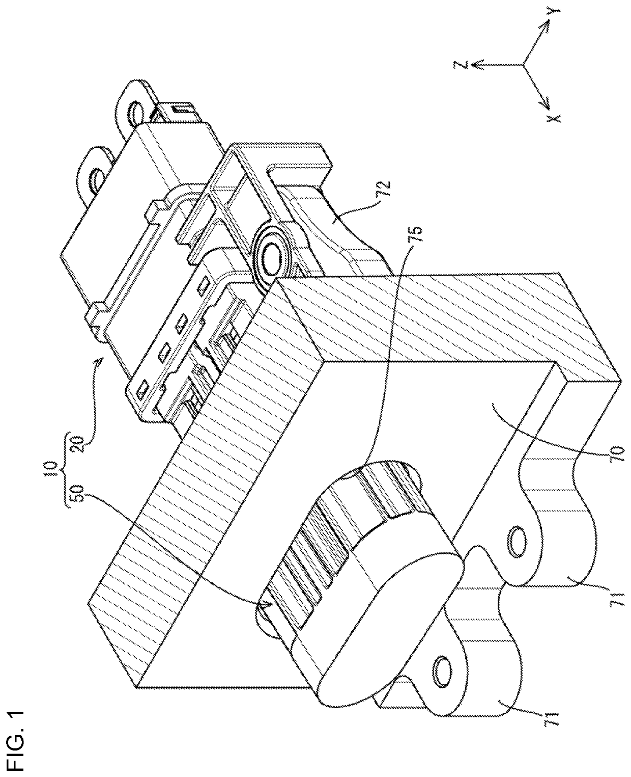
[0044]A connector 10 of this embodiment is disposed in a power supply path of a vehicle such as an automotive vehicle and, as shown in FIG. 1, is mounted on a case 70 (only a part of the case 70 on the side of the connector 10 is shown and the other part is not shown in FIG. 1 and other figures) of a device and includes a first connector 20 and a second connector 50 to be connected to the first connector 20. In the following description, a connecting direction of the connectors 20, 50 is referred to as a forward direction and a Y direction and a Z direction of FIG. 1 are referred to as a leftward direction and an upward direction.

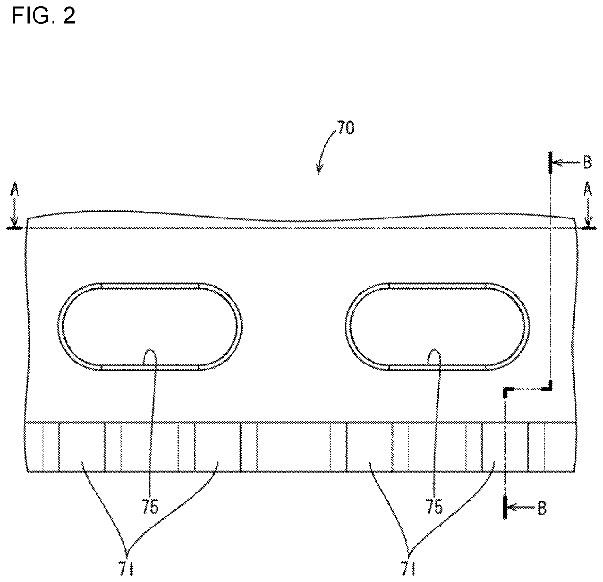
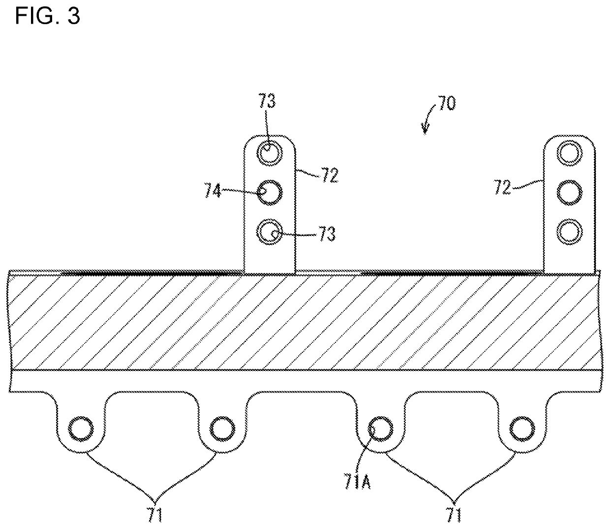
[0045]The case 70 is made, for example, of metal and a power storage module (not shown), such as a battery or a capacitor, is accommodated inside the case 70 on the side of the first connector 20. The case 70 is formed with an elliptical penetrating insertion hole 75 through which the second c...


PUM


Abstract

A connector (10) includes a first connector (20) and a second connector (50) to be connected to each other. The first connector (20) includes first terminals (21) and a first housing (23) configured to accommodate the first terminals (21). The second connector (50) includes second terminals (51) and a second housing (53) configured to accommodate the second terminals (51) and having a receptacle (54) to be fit to the first housing (23). A concave portion (30) is provided on a side of the first housing (23) to be fit to the second housing (53). The second housing (53) is provided with a pry preventing protrusion (62) projecting forwardly of the receptacle (54) and configured to suppress a positional deviation of the second housing (53) with respect to the first housing (23) by entering the concave portion (30) during a connecting operation.

Description

BACKGROUNDField of the Invention[0001]This specification relates to a connector.Related Art[0002]The expression “ply connection” refers to a connecting operation of a male connector and a female connector in postures inclined with respect to proper connecting postures. A pry connection can cause troubles due to contact of the connectors at positions where the connectors are not supposed to be in contact. Japanese Unexamined Patent Publication No. 2008-305607 discloses an assembly of a male connector and a female connector. The male connector has a receptacle and a lock receiving portion is on an outer surface of the receptacle. The female connector includes a lock arm for locking the male and female connectors in a connected state. The lock arm has a lock to be locked to the lock receiving portion and a pry preventing protrusion projects forward from the lock. The pry preventing protrusion interferes with the lock receiving portion when a connecting operation is performed with the c...

Claims


Application Information

Patent Timeline
Patent Type & Authority Patents(United States)
IPC IPC(8): H01R13/631H01R13/506H01R13/645H01R13/64
CPCH01R13/631H01R13/506H01R13/64H01R13/645H01R13/642H01R13/627H01R13/629H01R13/6315H01R13/516H01R13/74
Inventor KUDO, YASUHIRO
Owner SUMITOMO WIRING SYST LTD
Why Eureka
Try Eureka