Check patentability & draft patents in minutes with Patsnap Eureka AI!

Vibration actuator and electronic device including the same

a technology of vibration actuator and electronic device, which is applied in the direction of piezoelectric/electrostriction/magnetostriction machines, mountings, instruments, etc., can solve the problems of uneven rotation speed, increased load, and difficulty in manufacturing vibration actuators

Active Publication Date: 2021-05-18
CANON KK
View PDF15 Cites 0 Cited by
  • Summary
  • Abstract
  • Description
  • Claims
  • Application Information

AI Technical Summary

Benefits of technology

The design enables a more compact vibration actuator with reduced manufacturing complexity and improved sliding contact efficiency, enhancing the ease of assembly and performance by managing the gap between components effectively.

Problems solved by technology

Specifically, if the gaps are too small, load increases.
If the gaps are too large, the centrifugal whirling of the gear 210 and the rotor 207 becomes large, which causes uneven speed of rotation.
Thus, it is not easy to manufacture the vibration actuator.

Method used


Image

  • Vibration actuator and electronic device including the same
  • Vibration actuator and electronic device including the same
  • Vibration actuator and electronic device including the same

Examples


Embodiment Construction

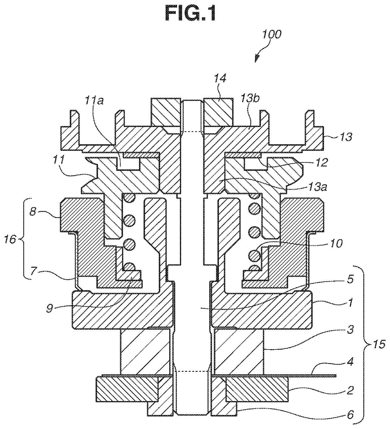
[0020]With reference to FIG. 1, a vibration actuator 100 according to a first exemplary embodiment is described. FIG. 1 is a schematic cross-sectional view illustrating the configuration of the vibration actuator (vibration driving apparatus) 100.

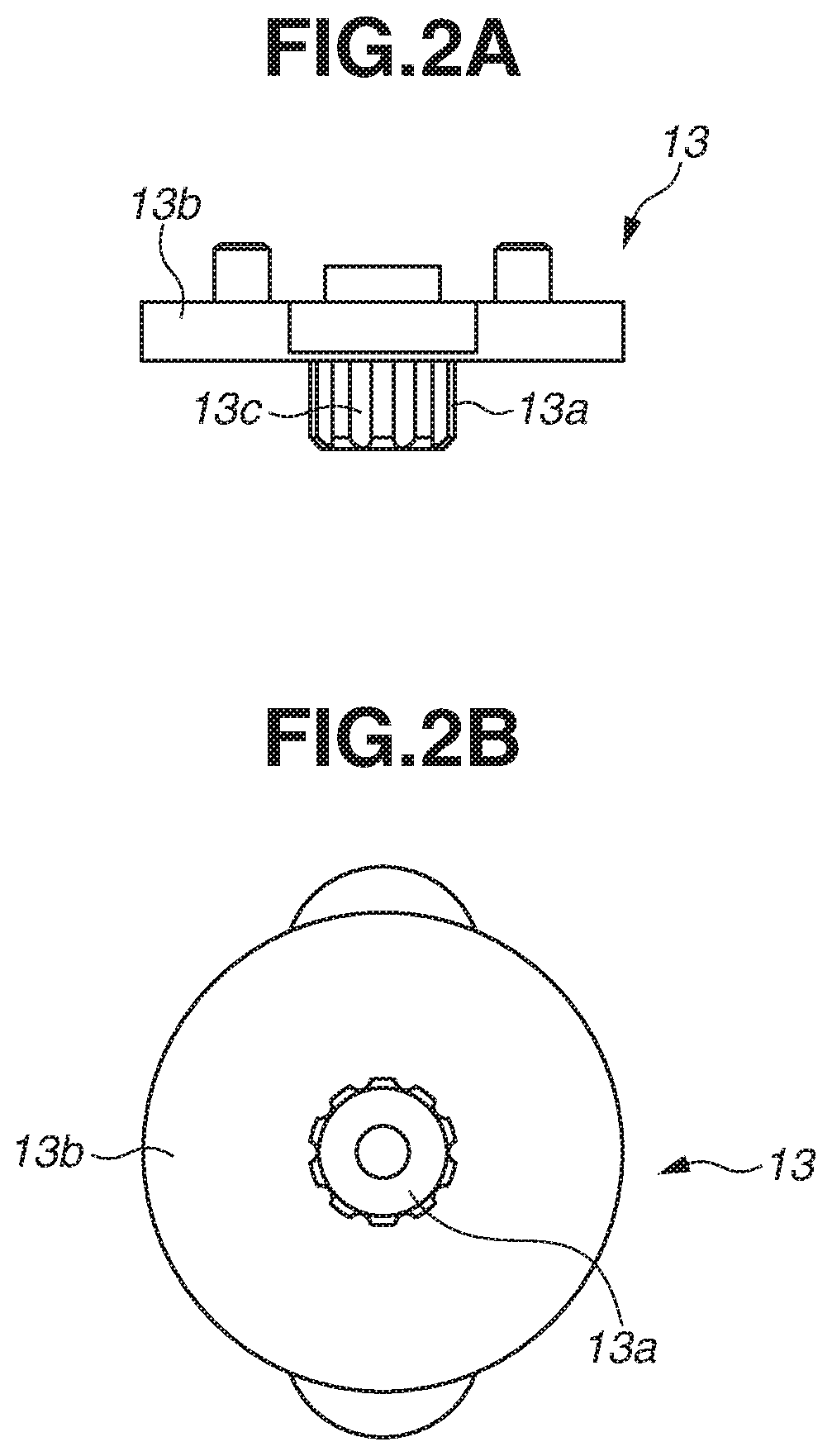
[0021]The vibration actuator 100 includes a rotor (rotating body) 16, a rubber 9, a pressure spring (pressure member) 10, a gear (output transmission member) 11, a flange cap (pressure reception member) 12, a flange (fixed member) 13, a first nut 14, and a vibrator 15. The vibration actuator 100 is a rotary vibration actuator.

[0022]The vibrator 15 includes a first elastic body 1, a second elastic body 2, a piezoelectric element (electro-mechanical energy conversion element) 3, a flexible printed circuit board 4, a shaft 5, and a second nut 6, In this case, a plurality of members included in the vibration actuator 100 is penetrated by the shaft 5. The plurality of members penetrated by the shaft 5 may include at least the rotating body 16, t...


PUM


Abstract

A vibration actuator includes a vibrator including a shaft, an output transmission member penetrated by the shaft, and configured to rotate about the axis of the shall, and a fixed member configured not to move relative to the shaft and configured to move relative to the output transmission member. The fixed member includes a base portion and a projection portion protruding from the base portion to the output transmission member side, the vibration actuator includes a pressure reception member between the base portion and the output transmission member in an axial direction of the shaft, and wherein the projection portion and the output transmission member are in contact with each other in a direction orthogonal to the axial direction of the shaft, and the projection portion and the output transmission member are not in contact with each other in the axial direction of the shaft.

Description

BACKGROUND OF THE INVENTIONField of the Invention[0001]The present invention relates to a vibration actuator including a vibrator and a rotating body that is frictionally driven by a vibration excited by the vibrator, and also relates to an electronic device including the vibration actuator.Description of the Related Art[0002]Generally, a vibration actuator is applied to a product to drive, for example, a camera lens. Japanese Patent Application Laid-Open No. 2016-13009 discusses a rod type vibration actuator.[0003]FIG. 7 is a schematic diagram illustrating the configuration of the conventional rod type vibration actuator. The rod type vibration actuator includes a vibrator 214, which excites driving vibrations. The rod type vibration actuator moves the vibrator 214 and a rotor (rotating body) 207, which is in pressure contact with the vibrator 214, relative to each other by the driving vibrations excited by the vibrator 214.[0004]The vibrator 214 includes at least two elastic bodie...

Claims


Application Information

Patent Timeline
Patent Type & Authority Patents(United States)
IPC IPC(8): H02N2/00H02N2/02G02B7/02H02N2/14H02N2/10H02N2/12
CPCH02N2/0015G02B7/02H02N2/0055H02N2/0065H02N2/026H02N2/103H02N2/106H02N2/123H02N2/147H02N2/006
Inventor SHIMADA, AKIRASEKI, HIROYUKI
Owner CANON KK
Features
  • R&D
  • Intellectual Property
  • Life Sciences
  • Materials
  • Tech Scout
  • Unparalleled Data Quality
  • Higher Quality Content
  • 60% Fewer Hallucinations
Learn More