Access control method and apparatus for use in mobile communication

a control method and mobile communication technology, applied in the field of mobile communication systems, can solve the problems of data cutoff, transmission latency, inability to dynamically adjust the drx cycle, etc., and achieve the effect of reducing signaling overhead, reducing data interruption time, and reducing signaling overhead

Active Publication Date: 2021-10-26
SAMSUNG ELECTRONICS CO LTD
View PDF23 Cites 0 Cited by
  • Summary
  • Abstract
  • Description
  • Claims
  • Application Information

AI Technical Summary

Benefits of technology

[0022]Also, the present disclosure aims to provide a method and apparatus for reducing the data interruption time during the handover of a UE and handling failure data interruption time reduction.
[0023]Also, the present disclosure aims to provide an operation mode transition method and apparatus of a UE for transitioning to a large paging area preference mode autonomously to reduce signaling overhead.
[0024]Furthermore, the present disclosure aims to provide a paging message-based operation mode transition method and apparatus of a UE for reducing signaling overhead.

Problems solved by technology

Meanwhile, with two DRX cycles (long DRX cycle and short DRX cycle) specified in LTE standard, it may be impossible to adjust the DRX cycle dynamically according to Data Radio Bearer (DRB) characteristics, traffic pattern, and buffer status.
In the LTE system, the negative acknowledgement (NACK) corresponding to a packet transmission trigger retransmission and thus may cause transmission latency.
Typically, the data interruption time lasts at least a few dozen milliseconds (ms), resulting in data cutoff.
This means that the network cannot manage the UEs in the light connected mode continuously but controls them to transition to the RRC Idle mode.
This operation for transitioning the UE operation mode from the light connected mode to the RRC Idle mode may cause significant signaling overhead.

Method used


Image

  • Access control method and apparatus for use in mobile communication
  • Access control method and apparatus for use in mobile communication
  • Access control method and apparatus for use in mobile communication

Examples


first embodiment

[0126]Detailed description of well-known functions and structures incorporated herein may be omitted to avoid obscuring the subject matter of the present disclosure. Exemplary embodiments of the present disclosure are described with reference to the accompanying drawings in detail.

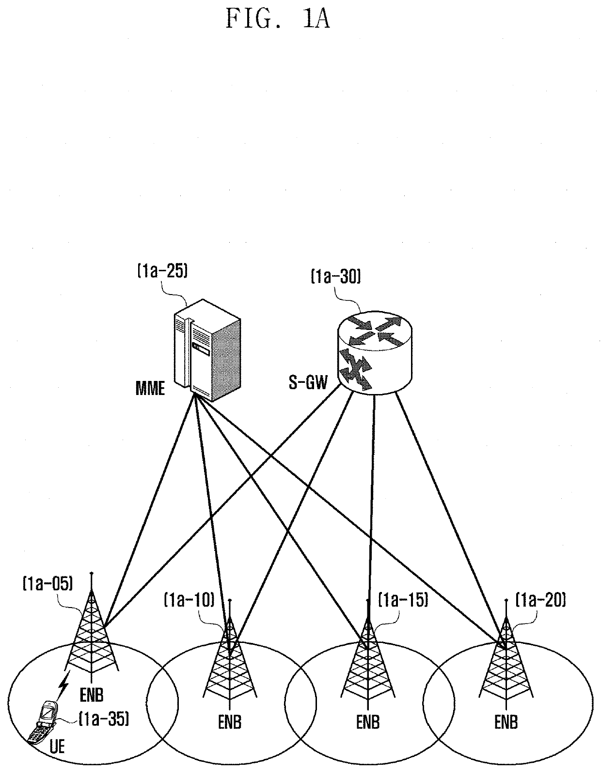
[0127]FIG. 1A illustrates an LTE system to which the present disclosure is applied.

[0128]In reference to FIG. 1A, the Radio Access Network (RAN) of the LTE system includes evolved Node Bs (eNBs) 1a-05, 1a-10, 1a-15, and 1a-20; a Mobility Management Entity (MME) 1a-25; and a Serving Gateway (S-GW) 1a-30. The User Equipment (UE) 1a-35 connects to an external network via the eNBs 1a-05, 1a-10, 1a-15, and 1a-20 and the S-GW 1a-30.

[0129]The eNBs 1a-05, 1a-10, 1a-15, and 1a-20 are equivalent to the legacy node Bs of the universal mobile telecommunications system (UMTS).

[0130]The UE 1a-35 connects to one of the eNBs via a radio channel, and the eNB has more control functions than the legacy node B. In the LTE sys...

second embodiment

[0229]This embodiment proposes a DRX operation capable of changing a DRX cycle and an inactivity timer dynamically.

[0230]FIG. 2A illustrates architecture of an LTE system to which the present disclosure is applied. The detailed description of the LTE system architecture has been made already with reference to FIG. 1A and thus is omitted herein.

[0231]FIG. 2B is a diagram illustrating a protocol stack of an interface between a UE and an eNB in the LTE system to which the present disclosure is applied.

[0232]In reference to FIG. 2, the protocol stack of the interface between the UE and the eNB in the LTE system includes a plurality of protocol layers stacked from the bottom to the top: physical (PHY) layer denoted by reference numbers 2b-20 and 2b-25, medium access control (MAC) layer denoted by reference numbers 2b-15 and 2b-30, radio link control (RLC) layer denoted by reference numbers 2b-10 and 2b-35, and packet data convergence control (PDCP) layer denoted by reference numbers 2b-0...

third embodiment

[0412]FIG. 3A illustrates architecture of an LTE system. The detailed description of the LTE system architecture has been made already with reference to FIG. 1A and thus is omitted herein.

[0413]FIG. 3B illustrates a protocol stack of an interface between a UE and an eNB in the LTE system.

[0414]In reference to FIG. 3B, the protocol stack of the interface between the UE and the eNB in the LTE system includes a PDCP layer denoted by reference numbers 3b-05 and 3b-40, an RLC layer denoted by reference numbers 3b-10 and 3b-35, a MAC layer denoted by reference numbers 3b-15 and 3b-30, and a PHY layer denoted by reference numbers 3b-20 and 3b-25.

[0415]The PDCP layer denoted by reference numbers 3b-05 and 3b-40 takes charge of compressing / decompressing an IP header, and the RLC layer denoted by reference numbers 3b-10 and 3b-35 takes charge of segmenting a PDCP PDU into segments of appropriate size.

[0416]The MAC layer denoted by reference number 3b-15 and 3b-30 allows for connection of mult...


PUM


Abstract

The present disclosure relates to a communication method and system for converging a 5th-Generation (5G) communication system for supporting higher data rates beyond a 4th-Generation (4G) system with a technology for Internet of Things (IoT). The present disclosure may be applied to intelligent services based on 5G communication technology and IoT-related technology, such as smart home, smart building, smart city, smart car, connected car, health care, digital education, smart retail, security and safety services. A handover method of a terminal in a mobile communication system according to the present disclosure includes transmitting UE capability information including a random access-free handover indicator to a first base station, receiving a handover command message from the first base station, and transmitting, when the handover command message includes uplink resource information, a handover complete message to a second base station based on the uplink resource information.

Description

CROSS-REFERENCE TO RELATED APPLICATIONS[0001]This application is a continuation of U.S. patent application Ser. No. 15 / 649,558 filed on Jul. 13, 2017, which is related to and claims priority to Korean Patent Application No. 10-2016-0088758 filed on Jul. 13, 2016, the disclosures of which are herein incorporated by reference in their entirety.BACKGROUND1. Field[0002]The present disclosure relates to a mobile communication system and, in particular, to a method for determining whether to bar an access in a mobile communication system.[0003]Also, the present disclosure relates to a method for configuring Discontinuous Reception (DRX) in a mobile communication system.[0004]Also, the present disclosure relates to a method for transmitting a paging signal to a terminal in a mobile communication system.[0005]Also, the present disclosure relates to a data transmission and reception method for Ultra-Reliable and Low-Latency Communication (URLLC) service in a mobile communication system.[0006...

Claims


Application Information

Patent Timeline
Patent Type & Authority Patents(United States)
IPC IPC(8): H04W36/00H04W72/04H04W74/08
CPCH04W36/0055H04W72/042H04W74/0833H04W36/0072H04W36/0077
Inventor KIM, SANGBUMKIM, DONGGUNSAYENKO, ALEXANDERJANG, JAEHYUKKIM, SOENGHUNVAN LIESHOUT, GERT JAN
Owner SAMSUNG ELECTRONICS CO LTD
Why Eureka
Try Eureka