Flood barrier

a flood barrier and floodwater technology, applied in the field of flood barriers, can solve the problems of limited life, prone to sliding of membranes, affecting the safety of workers, and reducing so as to reduce the risk of floodwater sliding

Active Publication Date: 2021-11-09
EINSTEIN IP
View PDF22 Cites 0 Cited by
  • Summary
  • Abstract
  • Description
  • Claims
  • Application Information

AI Technical Summary

Benefits of technology

[0013]The skirt allows sealing against uneven ground by the hydrostatic load imparted onto the ground by floodwater. The mechanically connected membrane sheet is integral with the first beam once connected. The mechanical connection ensures the skirt and structural elements of the barrier act as one and in doing so reduce the risk of sliding of the membrane sheet. The present invention is stable through reduced sliding risk, the elements allow rapid deployment from the protected side of the barrier, therefore it is more efficient and safer than prior art systems.
[0037]Preferably the skirt formed by the membrane extends outwardly from said first beam by at least a predetermined length that is sufficient such that hydrostatic forces acting upon the skirt will overcome sliding forces imparted on the flood barrier by floodwaters. The inventors have realised that by providing a skirt that is sufficiently long, it can not only provide a seal against the ground, but also to reduce the risk of sliding of the flood barrier due to the action of floodwaters on the barrier. The predetermined skirt length is preferably equal to or above the length at which the force from the mass of water acting on the skirt will overcome sliding forces on the flood barrier.

Problems solved by technology

Tubes and flexible membranes are known for use in portable flood barriers but have limited life and demonstrate vulnerability to floating debris, high flow currents and waves.
Membranes may be prone to sliding if anchoring is not undertaken, tubes may be vulnerable to sliding, rolling and collapse.
A disadvantage with these type of barriers is that they are generally reliant on a membrane to be draped over the system.
This means that they are not sufficiently water-tight until the entire system is erected and covered by the membrane.
This significantly impacts their effectiveness as deployment time renders their application inappropriate due to lack of manpower or available warning time.
The use of a membrane is also a problem in its extension of the required footprint with no resultant increase in stability.
These systems remain prone to sliding especially on surfaces such as wet concrete or asphalt.
These problems can be overcome by anchoring the stanchions, however this is resisted by many highways authorities and municipalities, or by loading with weight such as sandbags, however this increases the deployment time for the system and requires further manpower.
Another major problem with metal flood barriers is the requirement of operatives to carry out operations on the flood-side of the barrier.
In instances of deployment in rising water, this causes a significant problem in getting the membrane into position on the ground with anchor chains or sandbags on top.
This can produce a significant health and safety risk and one which is exacerbated by isolation of the flood-side of a barrier extending perhaps many hundreds of metres.
However, there is a great deal of friction as the beam is slid against a vertical gasket, making the beams hard to install.
This U-channel is typically only to the height of the bottom beam on a portable inclined barrier however the mobility of the stanchions and the frictions and tight tolerances against the vertical gasket make this operation problematic.
Removal of the beam during disassembly is even more difficult than installation of the beam.
Despite the use of soft thick gaskets on the bottom beam they fail to adequately seal on uneven ground.
The use of a membrane draped over the system would solve this but present the same disadvantages which are inherent in the panel systems.

Method used


Image

  • Flood barrier
  • Flood barrier
  • Flood barrier

Examples


Embodiment Construction

[0055]The present embodiments represent currently the best ways known to the applicant of putting the invention into practice. But they are not the only ways in which this can be achieved. They are illustrated, and they will now be described, by way of example only. Like reference numerals are used to refer to like components.

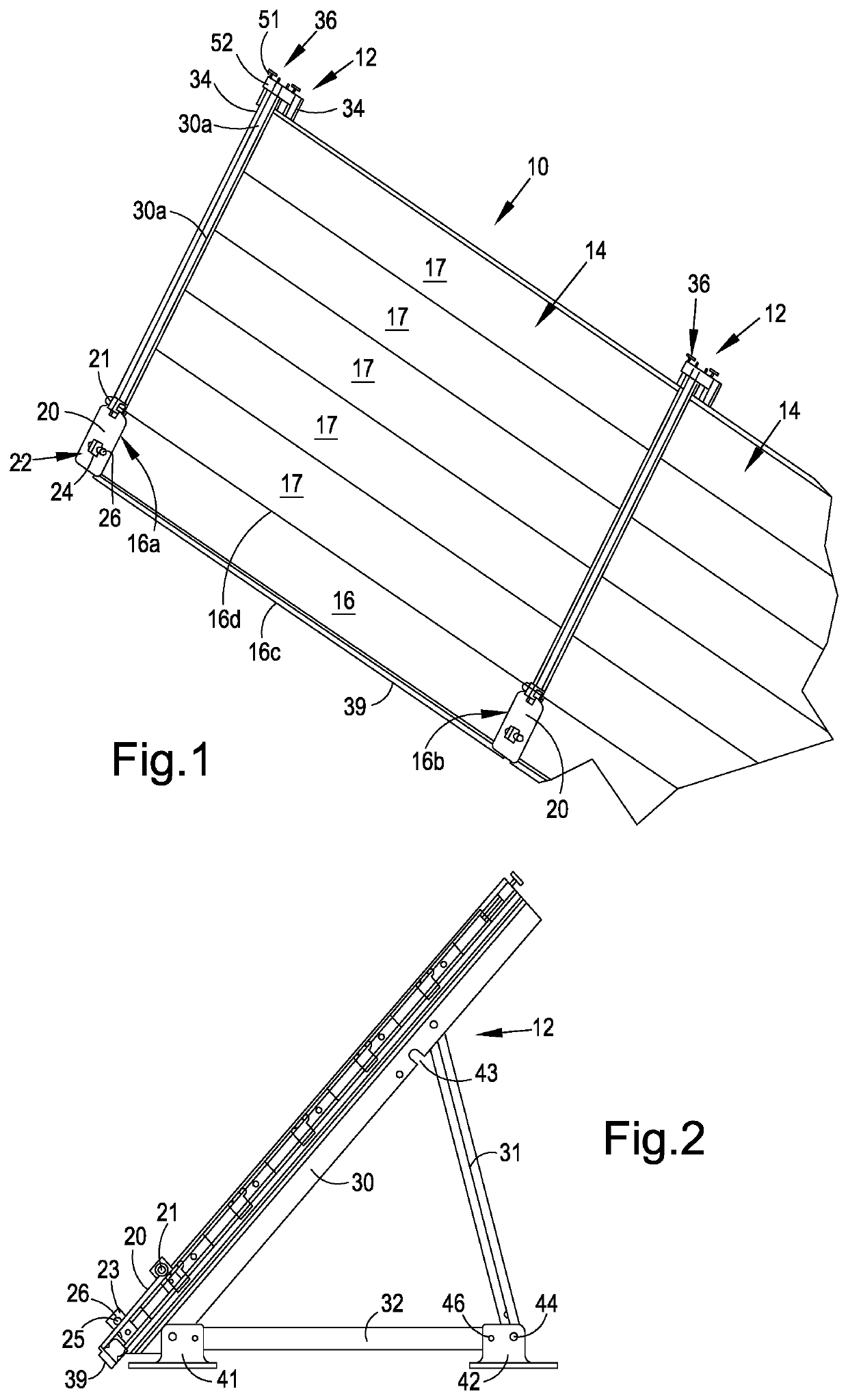
[0056]Referring to FIG. 1, an assembled flood barrier 10 is shown. Although an assembled flood barrier will be described, it will be understood that it can be provided as a kit such that it can be assembled / disassembled as required so that the barrier can function as a portable flood barrier. The flood barrier has a waterside to be placed adjacent a body of water and a protected side opposing the waterside. The flood barrier 10 has a plurality of stanchions or supports 12 and a plurality of intermediate barrier sections 14, one intermediate barrier section 14 disposed between each pair of neighbouring supports. In FIG. 1, two supports 12, one whole intermediate...


PUM


Abstract

A flood barrier to protect an area of land from floodwaters, the flood barrier having a waterside to be placed adjacent a body of water and a protected side opposing the waterside, the flood barrier comprising a plurality of supports spaced apart from one another; at least one intermediate barrier section supported to extend between a pair of neighbouring supports when assembled, the intermediate barrier section comprising at least a first beam arrangeable such that it is supported to extend between the corresponding pair of neighbouring supports and a water impermeable membrane sheet attachable to said first beam via a mechanical connection to form a skirt extending from said first beam, outwardly from the waterside of the flood barrier onto the ground.

Description

CROSS REFERENCE TO RELATED APPLICATIONS[0001]The present application is the U.S. national stage application of International Application PCT / GB2017 / 052099, filed Jul. 17, 2017, which international application was published on Jan. 18, 2018 as International Publication 2018 / 011605 A1. The International Application claims priority to Great Britain Application 1612363.0 filed Jul. 15, 2016.FIELD OF THE INVENTION[0002]The present invention relates to a flood barrier and in particular a portable flood barrier. The invention also relates to kits for flood barriers and methods for erecting such flood barriers.BACKGROUND TO THE INVENTION[0003]Portable flood barriers come in a number of forms each with its own set of relative advantages and disadvantages. Tubes and flexible membranes are known for use in portable flood barriers but have limited life and demonstrate vulnerability to floating debris, high flow currents and waves. Membranes may be prone to sliding if anchoring is not undertaken...

Claims


Application Information

Patent Timeline
Patent Type & Authority Patents(United States)
IPC IPC(8): E02B3/10E02B3/16
CPCE02B3/106E02B3/16E02B3/10E02B7/20
Inventor WARD, NICHOLAS
Owner EINSTEIN IP
Why Eureka
Try Eureka