
Sunshade and a method of constructing a sunshade

a technology of sunshade and sunshade frame, which is applied in the direction of sunshade, doors/windows, sunshade, etc., can solve the problems of reducing the passage of sunshine, low efficiency, and the efficiency of sunshine admission peaks at noon but falls off sharply, so as to achieve the effect of maximising the admission of sunshin

Active Publication Date: 2022-04-19
SANTA CLAUS O
View PDF9 Cites 0 Cited by
  • Summary
  • Abstract
  • Description
  • Claims
  • Application Information

AI Technical Summary

Benefits of technology

The invention provides a sunshade element which is designed to maximize the amount of sunshine that enters a shaded area during winter and blocks sunshine during the summer. The sunshade element has a thin profile that is viewed as a reference path between adjacent openings, which helps to guide sunshine in the most efficient way. The sunshade element can be made up of multiple segments that are spaced apart from each other to improve the admission of sunshine in the winter and to block sunshine in the summer. Overall, this invention helps to create a sunshelf that provides effective blocking and admission of sunshine for the entire year.

Problems solved by technology

AU600371 employs slats of considerable thickness, which reduce the passage of sunshine and results in low efficiency.
In particular, AU600371 does not take into consideration the three dimensional movements of the Sun, with the result that the efficiency of sunshine admission peaks at noon but falls off sharply before and after noon over the annual solar cycle.
However, it suffers the same deficiency as AU600371 and other known devices in failing to maintain efficiency of sunshine admission before and after noon over the annual solar cycle.
Moreover, these prior art sunshades are horizontal slat devices and so cannot be integrated to form part of a sloping roof, or respond to the three dimensional movements of the Sun.

Method used


Image

  • Sunshade and a method of constructing a sunshade
  • Sunshade and a method of constructing a sunshade
  • Sunshade and a method of constructing a sunshade

Examples


second embodiment

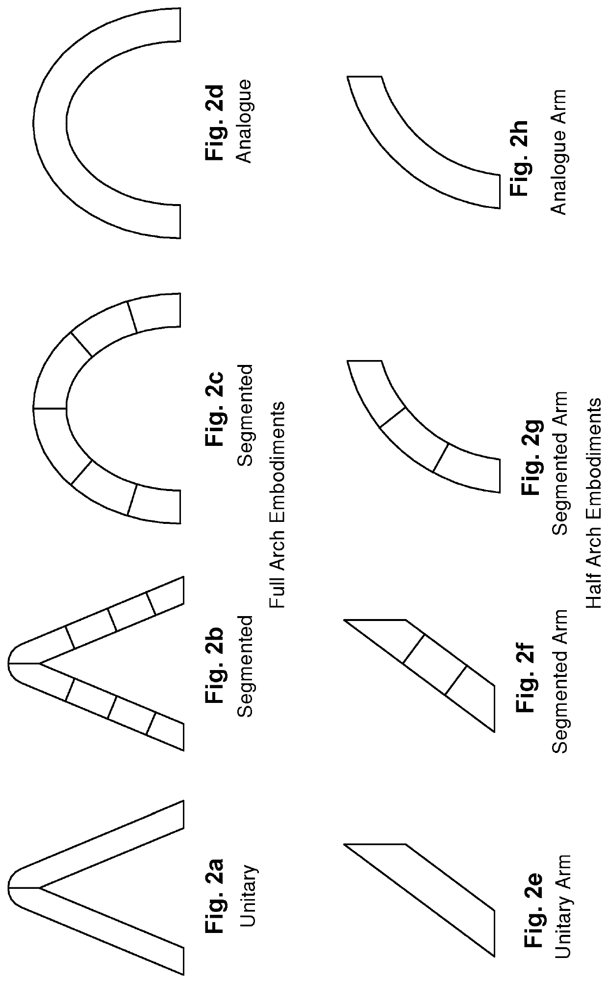
[0100]In a second embodiment, as shown in FIGS. 4a to 4c, each sunshade element 2 is formed by two interconnected slats or arms 4 comprised of interconnected segments 7 of segment length 8. For simplicity and clarity the minimum number of slat segments is shown in the embodiment of FIGS. 4a to 4c.

[0101]In the third arcuate embodiment utilising a plurality of slat segments, FIGS. 5a to 5c, the slat segments combine to form a segmented arcuate shape or profile. It will be appreciated that the more slat segments there are, the closer the segmented arcuate slat approximates an analogue arcuate slat. Again, for simplicity and clarity the minimum number of slat segments is shown in the embodiment of FIGS. 5a to 5c.

[0102]In a fourth, particularly efficient, embodiment, as shown in FIGS. 6a to 6c, each sunshade element 2 is a slat forming an analogue arcuate arch having a slat width 5 substantially normal to an arcuate slat length 6. The slat width 5 at each point along the arcuate slat l...

fourth embodiment

[0104]Each sunshade element 2 in the fourth embodiment is physically a single, continuous entity, although conceptually it is desirable to consider it as a two armed element formed by two connected segments 4.

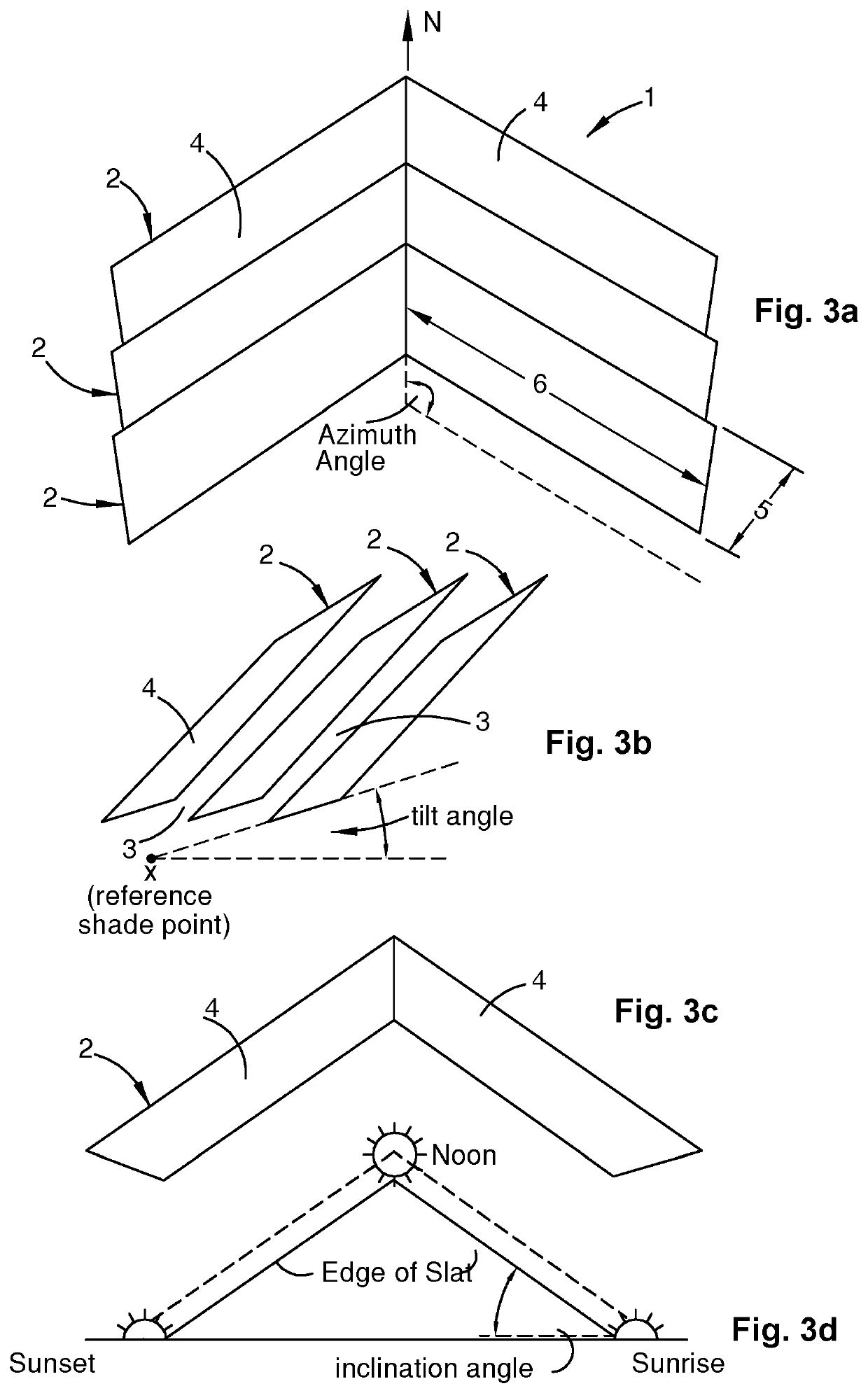
[0105]In the embodiments described above, it will be appreciated that although each sunshade element, when viewed from the reference shade point, approximates the reference solar path to varying degrees, each sunshade element minimises it profile to the sunrays in winter, thereby maximising the admission of sunshine to the shade area in winter. Similarly, it can be seen that each sunshade element approximates, albeit to varying degrees, a portion of the surface defined by straight lines extending between the reference shade point and the reference solar path.

[0106]In the above embodiments, the sunshade elements 2 are substantially identical, each with a substantially uniform width. The sunshade elements are spaced uniformly apart, with each aperture 3 having a substantially uni...

first embodiment

[0111]In another variation of all the embodiments, the shade area is adjacent a structure. In this variation of a basic form of the invention, each sunshade element includes just one slat arm 4 (half-arch), arranged such that the sunshade element 2 cooperates with the structure to provides effective blocking and admission of sunshine to the shade area over the annual solar cycle. For example, the sunshade may be positioned on the eastern or western slope of a hip roof to provide coverage over a skylight. Therefore, the skylight, being the shade area in this case, would only be exposed to approximately one half of the diurnal cycle, and would only require one slat arm 4 to provide adequate coverage. In another example, the sunshade is applied as an awning on the eastern side of a tall building. In other words, the full-arch sunshade described in the initial first embodiment is applied to situations where sunshine is available throughout most of the day, whilst the half-arch sunshade ...


PUM


Abstract

The present invention relates to sunshades and methods of constructing sunshades, particularly, sunshade canopies installed at a fixed location in the temperate zones.In a first aspect of the invention, a sunshade element is configured such that the sunshade element is viewed from a reference shade point as a thin profile between adjacent apertures over predetermined days in winter, thereby maximising the admission of sunshine to the shade area; and configured such that the sunshade element presents the maximum or near maximum breadth of its during predetermined days in summer; resulting in the admission of sunshine in winter and the blocking of sunshine in summer. During the spring period winter, sunshine is gradually replaced by summer shade, and during the autumn period, summer shade is replaced by winter sunshine, such that the sunshade elements provide effective blocking and admission of sunshine to the shade area over the annual solar cycle.

Description

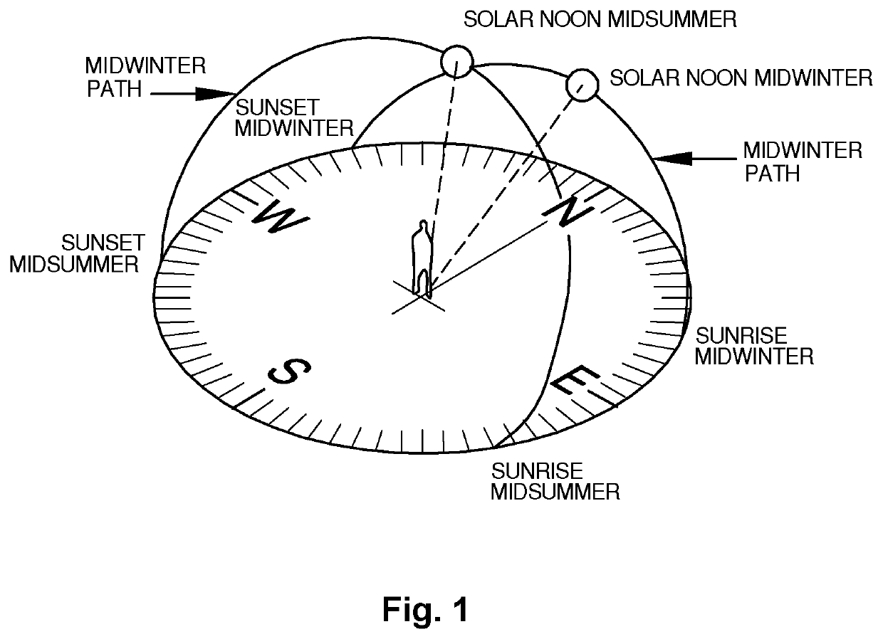
CROSS-REFERENCE TO RELATED PATENT APPLICATIONS[0001]The present application is a U.S. national stage application under 35 U.S.C. § 371 of PCT Application No. PCT / AU2018 / 051092, filed Oct. 10, 2018. The disclosure of the aforementioned priority application is incorporated herein by reference in its entirety.FIELD OF THE INVENTION[0002]The present invention relates to sunshades and methods of constructing sunshades, particularly, sunshade canopies installed at a fixed location in the temperate zones.BACKGROUND OF THE INVENTION[0003]Any discussion of the prior art throughout this specification should in no way be considered as an admission that such prior art is widely known or forms part of the common general knowledge in the field.[0004]FIG. 1 illustrates the path of the Sun over the course of a day in mid-winter and mid-summer over the course of a year at latitude 34 degrees south.[0005]Over the course of a day in the temperate zones, shadows move continuously as the Sun passes from...

Claims


Application Information

Patent Timeline
Patent Type & Authority Patents(United States)
IPC IPC(8): E04F10/10
CPCE04F10/10E04F10/08E06B9/386
Inventor SANTA CLAUS, O
Owner SANTA CLAUS O
Learn More