Network design device, network design method, and network design processing program

a network design and network technology, applied in the direction of transmission, electrical equipment, etc., can solve the problem of increasing the cost of network equipmen

Active Publication Date: 2022-07-05
NIPPON TELEGRAPH & TELEPHONE CORP
View PDF5 Cites 0 Cited by
  • Summary
  • Abstract
  • Description
  • Claims
  • Application Information

AI Technical Summary

Benefits of technology

[0035]According to the first to fifth aspects of the present invention, the number of redundant paths for each line is calculated and the path candidate set is calculated for each line on the basis of the calculated number of redundant paths in an optimization problem for calculating an optimal network configuration that minimizes the total cost value in the overall network. Thereby, it is possible to provide a network design apparatus, a network design method, and a network design processing program capable of designing an optimal network configuration for an infrastructure network with a plurality of types of required degrees of path redundancy in the calculation of the optimization problem.
[0036]Further, in the second aspect and the third aspect of the present invention, the number of redundant paths for each line is calculated on the basis of the acquired required degree of path redundancy of each line. Thus, in the calculation of the optimization problem, it is possible to more appropriately derive an optimal network configuration for an infrastructure network with a plurality of types of required degrees of path redundancy.
[0037]Further, in the third aspect of the present invention, the path candidate set including path candidates including different path sets is calculated in the calculation of the path candidate set for each line. Thus, in the calculation of the optimization problem, it is possible to more appropriately derive an optimal network configuration for an infrastructure network with a plurality of types of required degrees of path redundancy.

Problems solved by technology

With the increase in the number of services or the diversification of the requirements, a cost of equipment of the network has increased.

Method used


Image

  • Network design device, network design method, and network design processing program
  • Network design device, network design method, and network design processing program
  • Network design device, network design method, and network design processing program

Examples


first embodiment

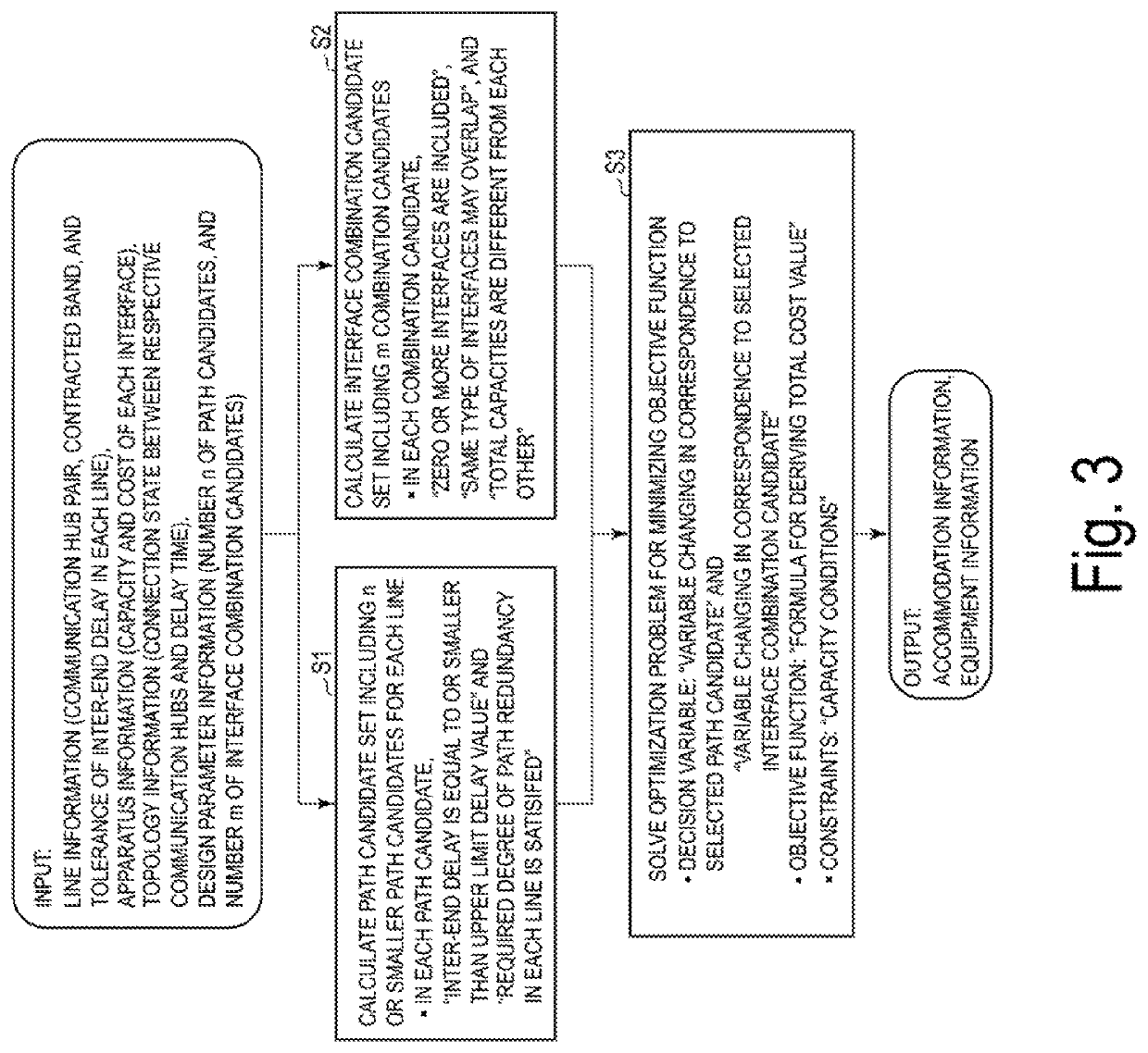
[0049]In a first embodiment, path candidates satisfying a required degree of path redundancy of each line are calculated. This allows a network configuration capable of accommodating a plurality of lines having different required degree of path redundancy to be derived.

[0050]Apparatus

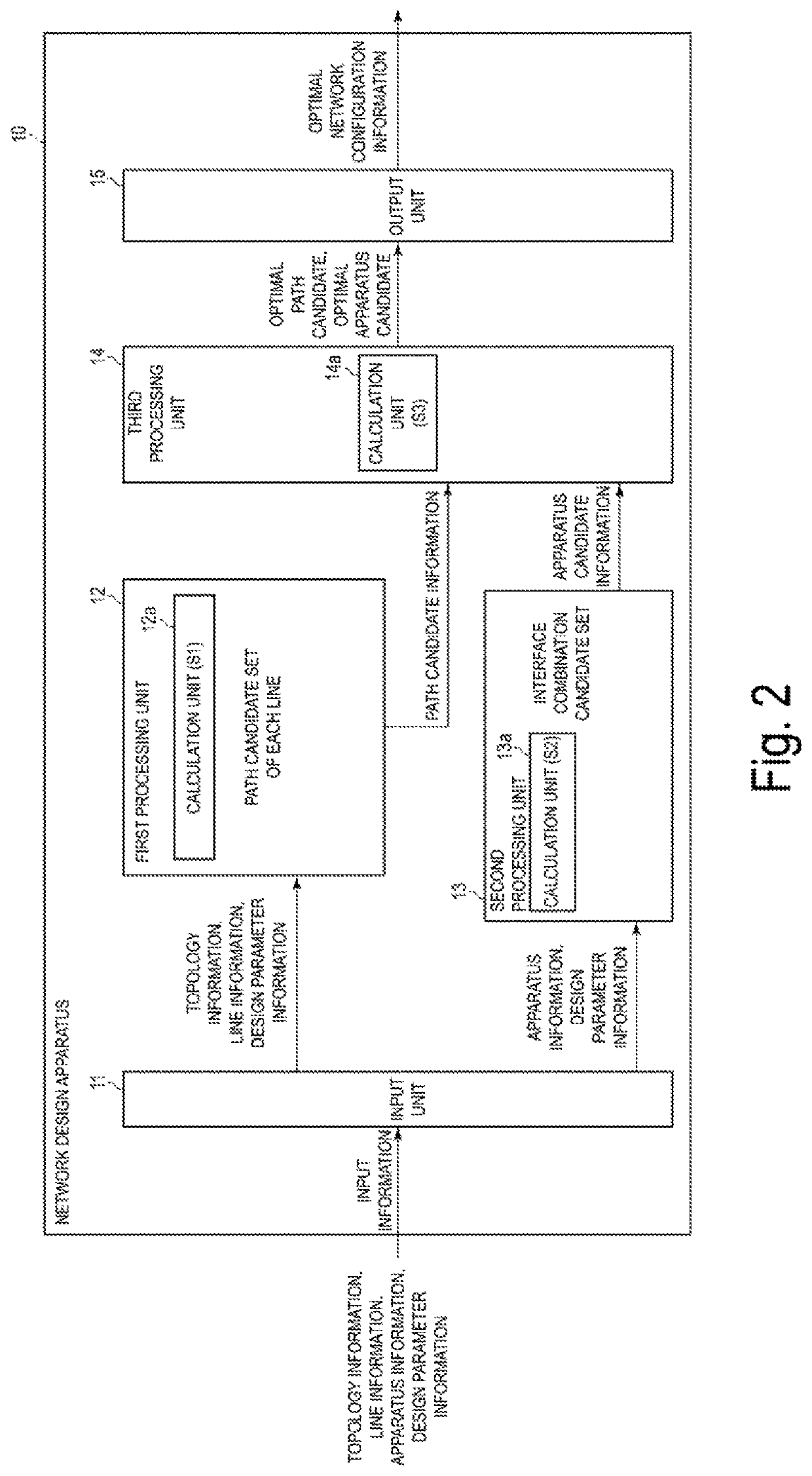
[0051]An example of a network design apparatus of the first embodiment is shown. FIG. 2 is a diagram illustrating an example of the network design apparatus according to the first embodiment of the present invention. The network design apparatus 10 outputs optimal network configuration information including optimal path information and optimal equipment information on the basis of input information. The network design apparatus 10 includes an input unit (input reception unit) 11, a first processing unit 12, a second processing unit 13, a third processing unit 14, and an output unit (generation unit) 15.

[0052]The first processing unit 12 includes a calculation unit 12a. The second processing unit 13 incl...

operational example

An operation example in the first embodiment divided into an example of input information and an operation example of each process will be described.

[0097]Example of Input Information

[0098]Topology Information

[0099]FIG. 6 is a diagram illustrating an example of the topology. FIG. 7 is a diagram illustrating a model example for use in the example of the topology in FIG. 6. That is, FIG. 7 is a diagram illustrating, for example, symbols used in the example in FIG. 6. In FIG. 7, communication hub “1” indicates a communication hub with the communication hub number of 1. Further, in FIG. 7, link “1” indicates a link with a link number of 1 and is connected to communication hub “1”.

[0100]FIG. 6 illustrates a connection state between communication hubs. Specifically, a connection state of communication hubs corresponding to communication hubs “1” to “4” via link “1” to link “5” is shown. The connection matrix M indicating the connection state between the communication hubs in the example o...


PUM


Abstract

With a network design apparatus, a network design method, and a network design processing program, a network configuration is designed for a network in which a transfer apparatus is disposed at each of a plurality of communication hubs and the communication hubs are connected via a link by a link portion apparatus in the transfer apparatus. In design of a network configuration, a threshold value of an inter-end delay and the number of redundant paths are calculated for each line on the basis of topology information, line information, and design parameter information. A path candidate set is calculated for each line on the basis of the threshold value of the inter-end delay and the number of redundant paths.

Description

CROSS-REFERENCE TO RELATED APPLICATIONS[0001]This application is a 371 U.S. National Phase of International Application No. PCT / JP2019 / 007804, filed on Feb. 28, 2019, which claims priority to Japanese Application No. 2018-041256 filed on Mar. 7, 2018. The entire disclosures of the above applications are incorporated herein by reference.TECHNICAL FIELD[0002]Embodiments of the present invention relate to a network design apparatus, a network design method, and a network design processing program.BACKGROUND ART[0003]In recent years, with the diversification of network services, the number of services has increased and requirements of a network for the services have diversified. Examples of the requirements for a network include an inter-end delay, band assurance, and conditions regarding redundancy. With the increase in the number of services or the diversification of the requirements, a cost of equipment of the network has increased.[0004]In order to curb the increase in cost, for exa...

Claims


Application Information

Patent Timeline
Patent Type & Authority Patents(United States)
IPC IPC(8): H04L41/14H04L41/0826H04L41/12H04L45/121H04L45/24
CPCH04L41/145H04L41/0826H04L41/12H04L45/121H04L45/24
Inventor TAKESHITA, ERINAKAWATA, HIDEOYOSHIHARA, SHINICHI
Owner NIPPON TELEGRAPH & TELEPHONE CORP
Why Eureka
Try Eureka