Robot apparatus and control method therefor

a robot and apparatus technology, applied in the field of robot apparatus, can solve the problems of increasing the robot may become inflexible to contact obstacles around the robot, and the robot may become necessary to charge the robot apparatus frequently, so as to achieve the effect of restraining the electric power consumption of the robot and flexibly executing the desired motion

Active Publication Date: 2014-08-26
TOYOTA JIDOSHA KK
View PDF14 Cites 2 Cited by
  • Summary
  • Abstract
  • Description
  • Claims
  • Application Information

AI Technical Summary

Benefits of technology

[0010]In the robot apparatus in accordance with this aspect, the robot controller may have a minimum-of-cost-function computation portion for calculating the minimum of the cost function, and the robot controller may drive the actuators so that the value of the cost function calculated by the minimum-of-cost-function computation portion becomes minimum. Due to this construction, the value of the cost function is minimized, and thus the electric power consumption can be minimized.
[0029]According to the invention, it is possible to provide a robot apparatus and a control method which are capable of flexibly executing desired motions while restraining the electric power consumption.

Problems solved by technology

In recent years, in conjunction with a robot apparatus that shares a space of activity with humans, there has arisen a situation in which as the electric power consumption of the robot apparatus has been increased, it has become necessary to frequently charge the battery of the robot apparatus.
Besides, there also is a technical issue that when a robot apparatus contacts a person, a thing, or the like around the robot apparatus, the robot apparatus needs to flexibly and safely have the contact and simultaneously execute a desired motion.
WO 00 / 43167, there is a possibility that, for example, a motion reference input from a user may constrain the motions of various joint axes of the robot more than necessary, and therefore the electric power consumption of the robot may increase and the robot may become unable to flexibly contact obstacles around the robot.
Similarly, with regard to the foregoing robot control apparatus shown in Japanese Patent No. 3283650, there is a possibility that motions of axes of the robot may be constrained, and therefore the electric power consumption of the robot may increase, or the robot may fail to execute a motion that satisfies a motion reference input when contacting an obstacle around the robot.

Method used


Image

  • Robot apparatus and control method therefor
  • Robot apparatus and control method therefor
  • Robot apparatus and control method therefor

Examples


Embodiment Construction

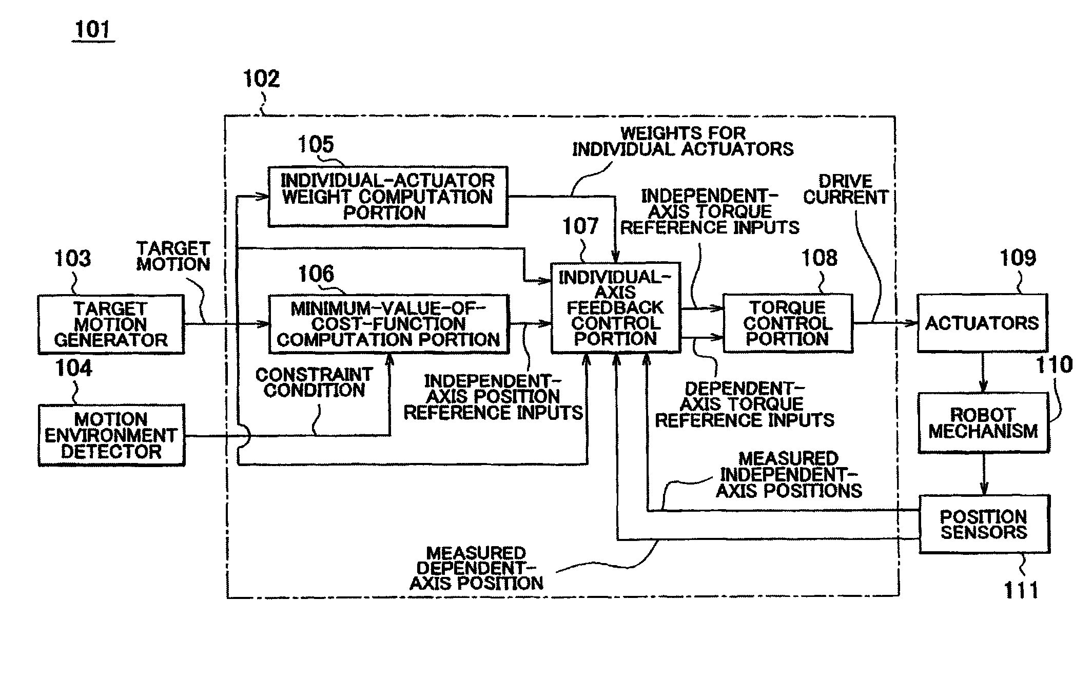
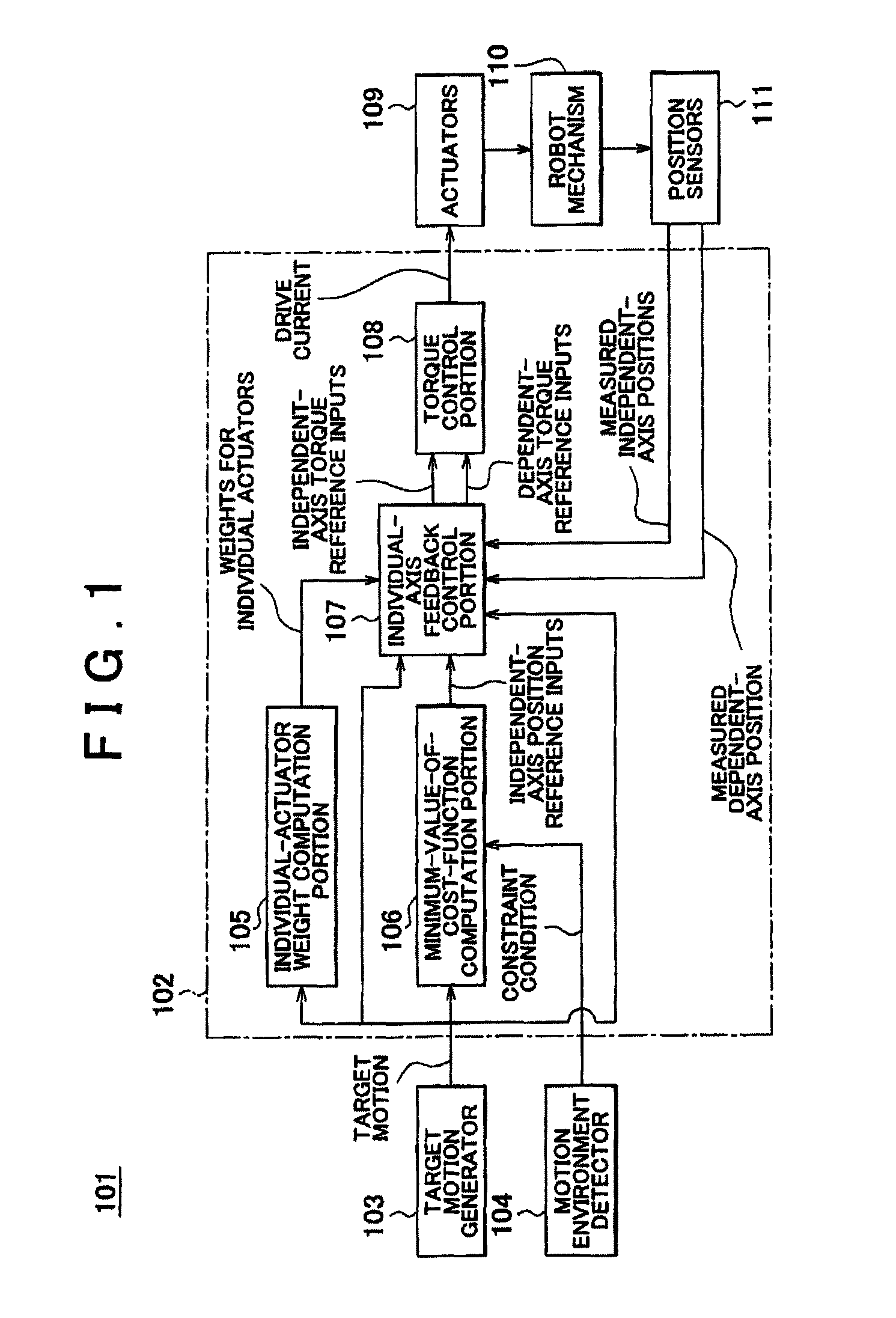
[0037]Hereinafter, embodiments of the invention will be described with reference to the accompanying drawings. FIG. 1 is a block diagram showing a general system construction of a robot apparatus in accordance with an embodiment of the invention. A robot apparatus 101 in accordance with this embodiment includes: a target motion generator 103, a motion environment detector 104, a plurality of actuators 109, a robot mechanism 110, a plurality of position sensors 111, and a robot controller 102.

[0038]The robot mechanism 110 is a movable portion of the robot, such as an arm portion, and a leg portion of the robot having a plurality of pivotable joint axes. Each joint axis is provided with an actuator 109 that rotationally drives the joint axis. Each joint axis is also provided with a position sensor 111 for detecting the position of the joint axis.

[0039]The target motion generator 103 generates, a target motion of each joint axis of the robot mechanism 110 which is a constraint equation...


PUM


Abstract

A robot apparatus includes a robot mechanism having a plurality of joints, and actuators that drive joint axes of the robot mechanism. The robot apparatus includes a robot controller that controls the driving of the actuators based on a cost function that is a function of torque reference inputs for the actuators.

Description

[0001]This is a 371 national phase application of PCT / IB2010 / 000574 filed 10 Mar. 2010, claiming priority to Japanese Patent Application No. 2009-058334 filed 11 Mar. 2009, the contents of which are incorporated herein by reference.BACKGROUND OF THE INVENTION[0002]1. Field of the Invention[0003]The invention relates to a robot apparatus that includes a robot mechanism that has a plurality of joints, and a plurality of actuators that drive joint axes of the robot mechanism, and to a control method for the robot apparatus. More particularly, the invention relates to a robot apparatus capable of flexibly executing desired motions while restraining the amount of electric power consumption, and to a control method for the robot apparatus.[0004]2. Description of the Related Art[0005]In recent years, in conjunction with a robot apparatus that shares a space of activity with humans, there has arisen a situation in which as the electric power consumption of the robot apparatus has been incre...

Claims


Application Information

Patent Timeline
Patent Type & Authority Patents(United States)
IPC IPC(8): G05B19/00B25J9/06B25J9/16
CPCB25J9/06B25J9/1633B25J9/1607B25J9/1615B25J9/1643B25J9/1666G05B2219/39217G05B2219/40343G05B2219/40359
Inventor ANDOH, FUKASHI
Owner TOYOTA JIDOSHA KK
Why Eureka
Try Eureka