Lighting tool for vehicle

a technology for vehicles and light fittings, applied in the direction of light and heating equipment, semiconductor devices for light sources, transportation and packaging, etc., can solve the problems of defect (dark section) and decreased efficiency of light emitted from light sources

Active Publication Date: 2022-09-13
STANLEY ELECTRIC CO LTD
View PDF10 Cites 0 Cited by
  • Summary
  • Abstract
  • Description
  • Claims
  • Application Information

AI Technical Summary

Benefits of technology

[0027]According to the aspect of the present invention, it is possible to provide a lighting tool for a vehicle capable of obtaining a good light distribution pattern.

Problems solved by technology

However, in the lighting tool for a vehicle disclosed in PCT International Publication No. 2018 / 043663, since an air layer (air gap) is present between the two light guide members, efficiency of utilization of the light emitted from the light source is decreased due to Fresnel loss generated therebetween.
Further, when the light is totally reflected between an upper surface of the lower light guide member and the air layer, a defect (a dark section) may occur on the side of a lower section of the light distribution pattern for a high beam.

Method used


Image

  • Lighting tool for vehicle
  • Lighting tool for vehicle

Examples


first embodiment

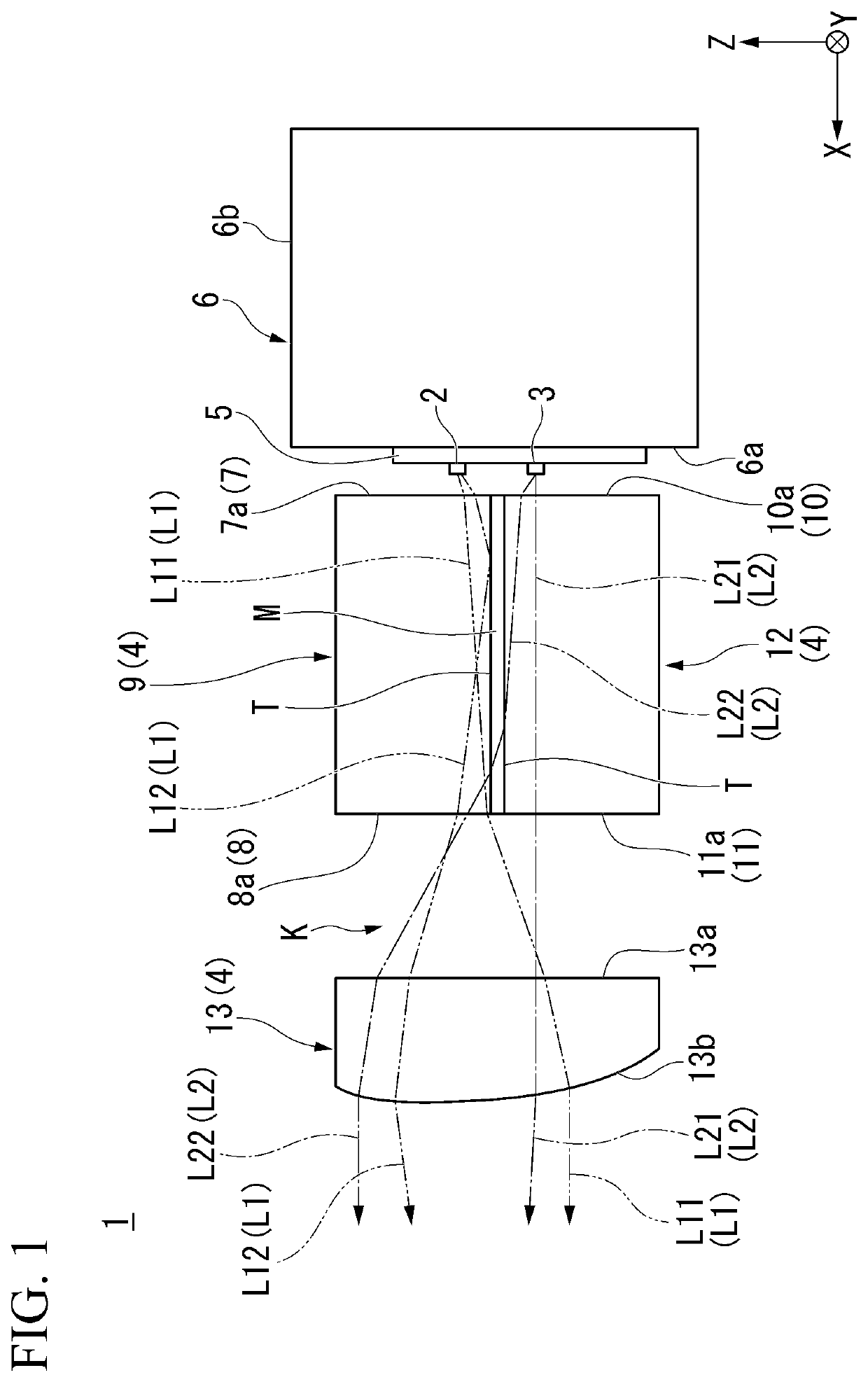
[0033]First, as a first embodiment of the present invention, for example, a lighting tool 1 for a vehicle shown in FIG. 1 and FIG. 2 will be described. Further, FIG. 1 is a cross-sectional view showing a configuration of the lighting tool 1 for a vehicle.

[0034]The lighting tool 1 for a vehicle of the embodiment is a headlight for a vehicle (headlamp) in which the present invention is applied, and is configured to emit a passing beam (low beam) that forms a light distribution pattern for a low beam including a cutoff line on an upper end thereof and a traveling beam (high beam) that forms a light distribution pattern for a high beam above the light distribution pattern for a low beam toward a front of the vehicle (in a +X-axis direction) in a switchable manner.

[0035]Specifically, as shown in FIG. 1, the lighting tool 1 for a vehicle generally includes a first light source 2 configured to emit first light L1, a second light source 3 configured to emit second light L2, and a projection...


PUM


Abstract

A projection lens has a first lens body including a first incidence section disposed at a side facing a first light source and a first emitting section disposed at a side opposite to the first incidence section, and a second lens body including a second incidence section disposed at a side facing a second light source and a second emitting section disposed at a side opposite to the second incidence section, a structure in which the first lens body and the second lens body abut against each other via an intermediate layer which is interposed between facing boundary surfaces of the first lens body and the second lens body is provided, and a refractive index of the intermediate layer is smaller than a refractive index of the first lens body.

Description

CROSS-REFERENCE TO RELATED APPLICATION[0001]Priority is claimed on Japanese Patent Application No. 2020-123529, filed Jul. 20, 2020, the content of which is incorporated herein by reference.BACKGROUND OF THE INVENTIONField of the Invention[0002]The present invention relates to a lighting tool for a vehicle.Description of Related Art[0003]For example, a lighting tool for a vehicle such as a headlight for a vehicle (headlamp) or the like includes a light source, a reflector configured to reflect light emitted from the light source in a direction in which the vehicle advances, a shade configured to shield (cut) some of the light reflected by the reflector, and a projection lens configured to project the light, some of which is cut by the shade, in the direction in which the vehicle advances.[0004]In such a lighting tool for a vehicle, when a light source image defined by a front end of the shade is reversed and projected by the projection lens as a passing beam (low beam), a light dist...

Claims


Application Information

Patent Timeline
Patent Type & Authority Patents(United States)
IPC IPC(8): F21S41/25F21S41/24F21S41/43F21V5/04F21Y115/10F21W102/13
CPCF21S41/25F21S41/24F21S41/43F21V5/04F21W2102/13F21Y2115/10F21S41/143F21S41/151F21S41/265F21S41/663
Inventor SUGIHARA, YUKINISHIMURA, SHOTAHOSHINO, SHINYA
Owner STANLEY ELECTRIC CO LTD
Why Eureka
Try Eureka