Lighting tool for vehicle

a technology for vehicle lighting and tools, applied in the direction of road vehicles, vehicle components, lighting and heating apparatus, etc., can solve the problem of too sharp cutoff lines defined by the front end of the shade, and achieve good light distribution patterns

Active Publication Date: 2021-09-30
STANLEY ELECTRIC CO LTD
View PDF0 Cites 4 Cited by
  • Summary
  • Abstract
  • Description
  • Claims
  • Application Information

AI Technical Summary

Benefits of technology

The present invention provides a lighting tool for a vehicle that can spread its light in a well-controlled way. This means that the vehicle can have better visibility and can see things that are further away from it.

Problems solved by technology

Incidentally, in the above-mentioned lighting tool for a vehicle, since the light, some of which is cut by the shade, is projected in the direction of advance of the vehicle, there was a problem such that the cutoff line defined by the front end of the shade becomes too sharp.

Method used


Image

  • Lighting tool for vehicle
  • Lighting tool for vehicle
  • Lighting tool for vehicle

Examples


Embodiment Construction

[0049]Hereinafter, an embodiment of the present invention will be described in detail with reference to the accompanying drawings.

[0050]Further, in the drawings used in the following description, in order to make components easier to see, the dimensional scale may vary depending on the components, and dimensional ratios between the components are not always the same as actual ones.

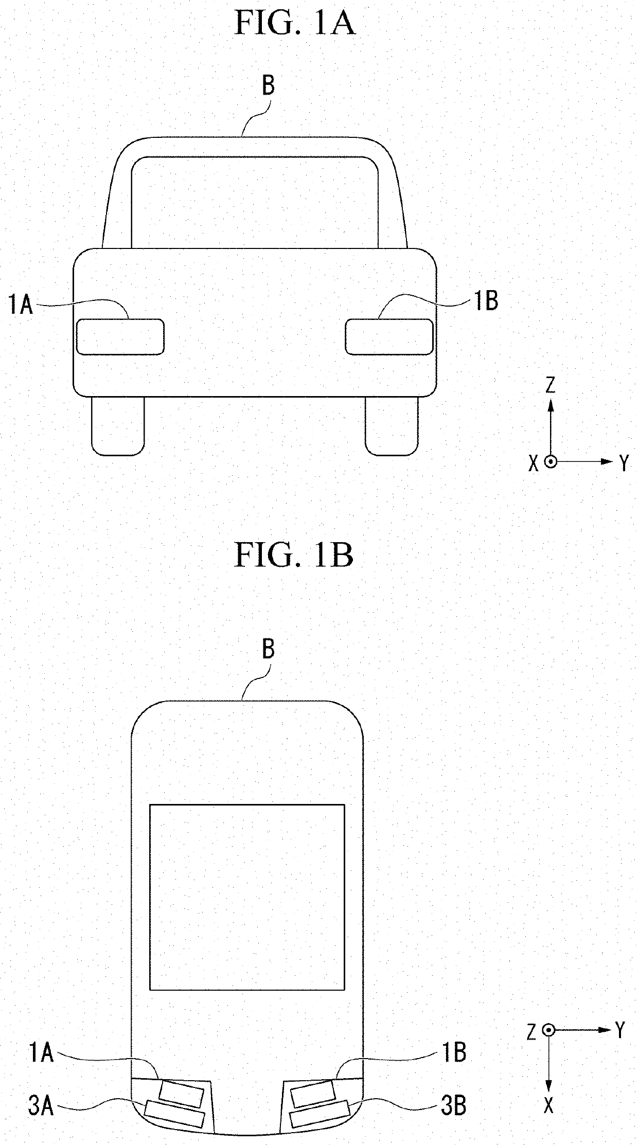
[0051]In addition, in the drawings described below, an XYZ orthogonal coordinate system is set, an X-axis direction indicates a forward / rearward direction (a lengthwise direction) of a lighting tool for a vehicle, a Y-axis direction indicates a leftward / rightward direction (a widthwise direction) of the lighting tool for a vehicle, and a Z-axis direction indicates an upward / downward direction (a height direction) of the lighting tool for a vehicle.

[0052]As an embodiment of the present invention, for example, lighting tools 1A and 1B for a vehicle shown in FIG. 1A and FIG. 1B will be described.

[0053]Further...


PUM


Abstract

A lighting tool for a vehicle includes a light source, and a projection lens configured to project light emitted from the light source forward, a light distribution pattern including a cutoff line at an upper end is formed with the light projected forward of the projection lens, and a refractive surface configured to refract some of the light projected forward of the projection lens in a specific direction is provided on a light emission surface of the projection lens.

Description

CROSS-REFERENCE TO RELATED APPLICATION[0001]Priority is claimed on Japanese Patent Application No. 2020-053271, filed Mar. 24, 2020, the content of which is incorporated herein by reference.BACKGROUND OF THE INVENTIONField of the Invention[0002]The present invention relates to a lighting tool for a vehicle.Description of Related Art[0003]For example, a lighting tool for a vehicle such as a headlight (headlamp) for a vehicle or the like includes a light source, a reflector configured to reflect light emitted from the light source in a direction of advance of a vehicle, a shade configured to shield (cut) some of the light reflected by the reflector, and a projection lens configured to project the light, some of which is cut by the shade in the direction of advance of the vehicle.[0004]In such a lighting tool for a vehicle, as a passing beam (low beam), a light distribution pattern for a low beam including a cutoff line at an upper end is formed by inverting and projecting a light sour...

Claims


Application Information

Patent Timeline
Patent Type & Authority Applications(United States)
IPC IPC(8): F21S41/265
CPCF21S41/265F21W2107/10F21S41/24F21S41/322F21S41/143F21S41/148F21W2102/155F21S41/255
Inventor NISHIMURA, SHOTA
Owner STANLEY ELECTRIC CO LTD
Why Eureka
Try Eureka