
Vehicle lamp

a technology for lamps and vehicles, applied in fixed installations, lighting and heating apparatus, instruments, etc., can solve the problems of reducing affecting the light distribution pattern, and affecting the positioning accuracy between the two components, so as to improve the positioning accuracy and improve the positioning accuracy. , the effect of increasing the positioning accuracy

Inactive Publication Date: 2014-09-30
KOITO MFG CO LTD
View PDF12 Cites 3 Cited by
  • Summary
  • Abstract
  • Description
  • Claims
  • Application Information

AI Technical Summary

Benefits of technology

The invention is related to a laser welding technology for joining together a lens and a lens holding member in a more accurate manner. The technical effects of the invention include: shortening of the working time of the welding operation, improved positioning accuracy between the lens and the lens holding member, prevention of unnecessary melting of the lens holding member and lens, and prevention of deformation of the gate mark. These technical effects can ensure good light distribution pattern and reliable joining of the lens and lens holding member.

Problems solved by technology

This leads to the generation of strain between the lens and the annular joining portion.
Thus, the positioning accuracy between the two components may become deteriorated.
Consequently, it is not possible to eliminate the reduction in positioning accuracy between the lens and the joining annular portion due to the generation of stain based on the accuracy of the flatness.
Accordingly, a high accuracy control is required with respect to the lens and the lens holding member, causing the production costs of the vehicle lamp to be increased greatly.

Method used


Image

  • Vehicle lamp
  • Vehicle lamp
  • Vehicle lamp

Examples


Embodiment Construction

[0027]Hereinafter, a vehicle lamp in accordance with embodiments of the invention will be described by reference to the accompanying drawings. In the embodiments of the invention described below, a vehicle lamp is applied to a vehicle headlamp. However, note that the applicability of the vehicle lamp of the invention is not limited to the vehicle headlamp, but can be applied to various types of vehicle lamps mounted on a vehicle body.

[0028]A vehicle headlamp 1 is mounted to be disposed at left and right end portions on a front end part of a vehicle body.

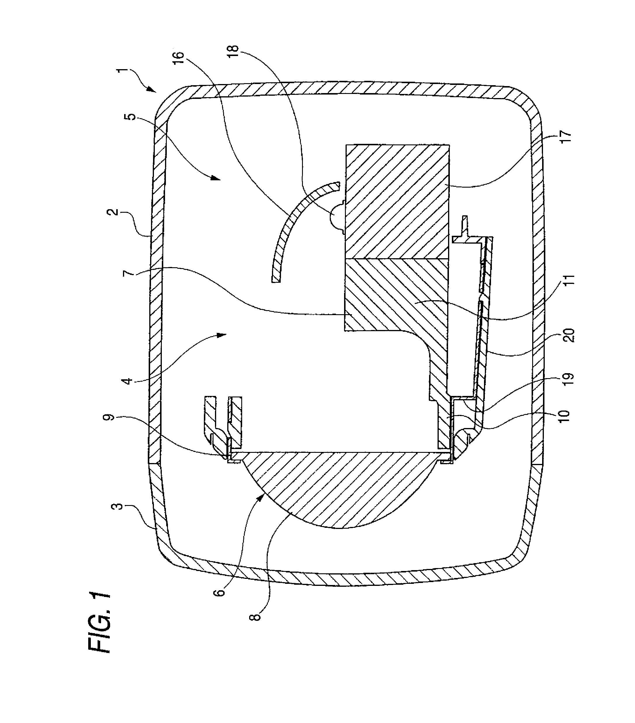
[0029]As is shown in FIG. 1, the vehicle headlamp 1 includes a lamp body 2 having a recess portion which is made to open to the front and a cover 3 adapted to close a front open side of the lamp body 2, and an interior space defined by the lamp body 2 and the cover 3 is made to constitute a lamp chamber 4.

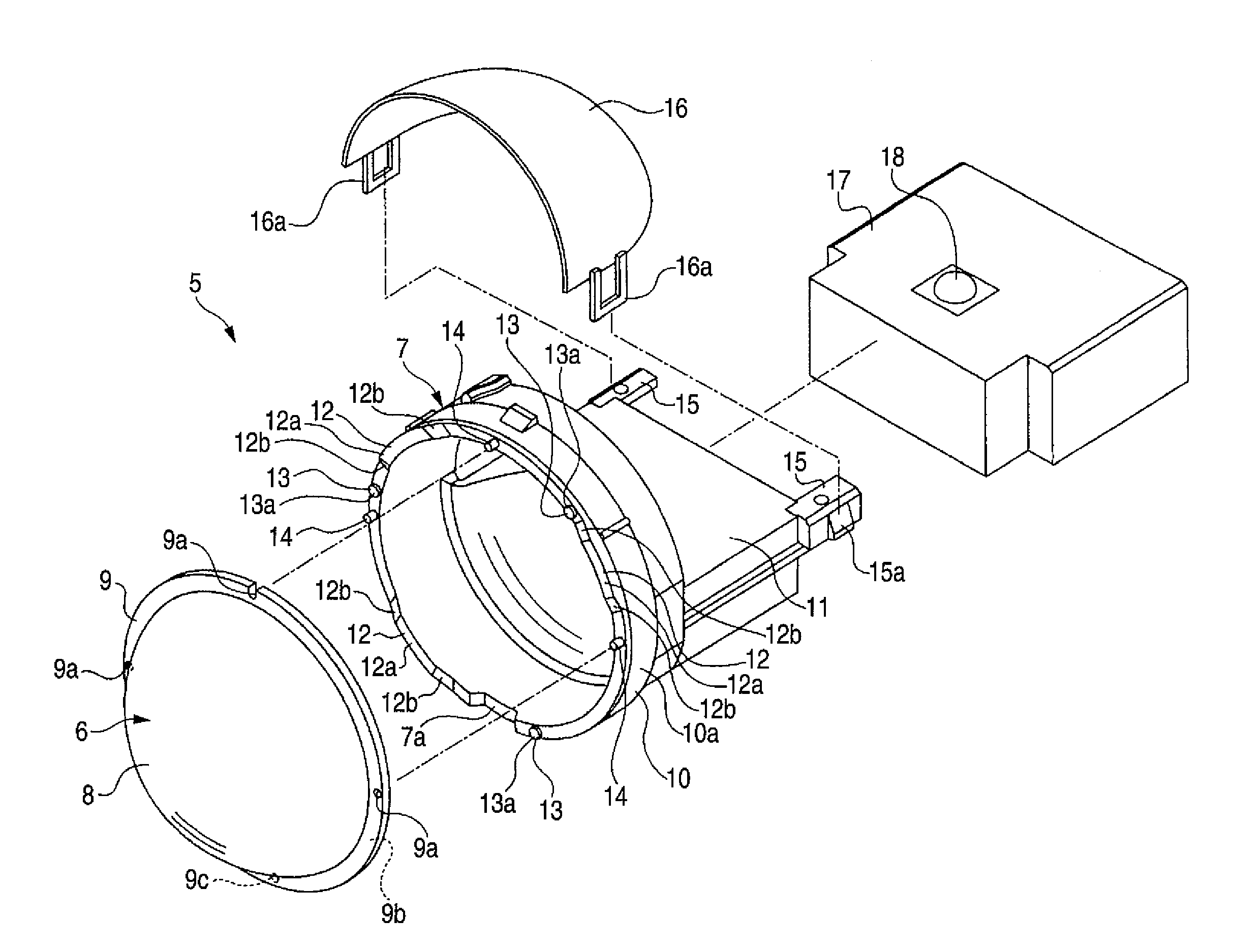
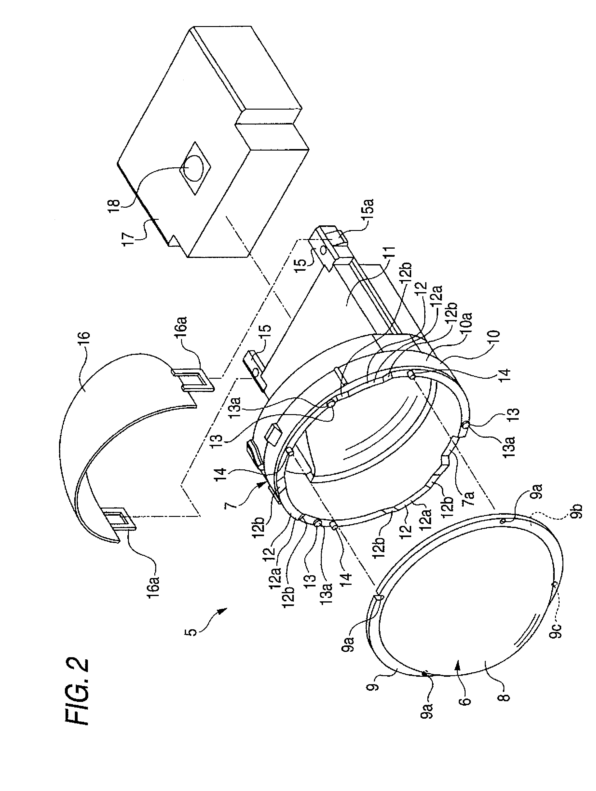
[0030]A lamp unit 5 is disposed in the lamp chamber 4. The lamp unit 5 is supported on the lamp body 2 by means of an optical axis...


PUM

PropertyMeasurementUnit
distancesaaaaaaaaaa
heightaaaaaaaaaa
reflection factoraaaaaaaaaa

Abstract

A vehicle lamp includes a lens formed from a resin material and a lens holding member for holding the lens formed from the resin material. The lens and the lens holding member are adapted to be joined together through laser welding. A joining annular portion is provided on the lens holding member to which an outer circumferential portion of the lens is joined. A plurality of welding portions and a plurality of stopper portions are provided on the joining annular portion. The plurality of welding portions project towards the lens and are positioned apart from each other in a circumferential direction. The plurality of stopper portions project towards the lens, are positioned apart from each other in the circumferential direction, and contact the outer circumferential portion of the lens when the lens is joined to the joining annular portion.

Description

BACKGROUND OF INVENTION[0001]1. Field of the Invention[0002]The present invention relates to a vehicle lamp, and more particularly to increasing the positioning accuracy between a lens and a lens holding member, which are joined together through laser welding, by providing pluralities of welding portions and stopper portions on the lens holding member in such a manner as to project towards the lens.[0003]2. Background Art[0004]In some of vehicle lamps, a lens and a lens holding member, such as a lamp body which holds the lens, are joined together through laser welding. Specifically, a joining annular portion is provided on the lens holding member to which an outer circumferential portion of the lens is joined, so that the joining annular portion of the lens holding member and the whole (the full circumference) of the outer circumferential portion of the lens are joined together through laser welding.[0005]When the outer circumferential portion of the lens and the joining annular por...

Claims


Application Information

Patent Timeline
Patent Type & Authority Patents(United States)
IPC IPC(8): G02B7/02B29C65/00B29C65/02B29C65/16B29C65/78B29K33/00B29K69/00B29L11/00B29L31/00B29L31/30F21S8/10F21Y101/02
CPCB29C65/16B29C66/348F21S48/1216B29C66/90B29C65/1635B29C66/542B29C65/1661B29C66/534F21S48/10B29L2031/30B29C65/7814B29C66/21B29C65/02B29C65/1677B29L2011/0016F21Y2101/02B29K2033/12B29K2069/00F21S48/1335B29C65/1674B29L2031/747B29C66/73921B29C66/71F21Y2115/10B29C66/114B29C66/131B29C66/24221B29C66/301F21S41/295F21S41/323F21S41/321F21S41/28F21S41/148F21S41/25F21S41/255F21S41/29F21S41/00
Inventor MATSUNAGA, CHIHARUKAGEYAMA, HIROYUKIINABA, TETSUAKI
Owner KOITO MFG CO LTD
Learn More