Vane motor

a technology of a motor and a shaft, applied in the direction of machines/engines, rotary/oscillating piston pump components, liquid fuel engines, etc., can solve the problems of only being able to operate, high oil consumption and thus operating costs, and unavoidable oil discharge into the environmen

Active Publication Date: 2022-09-20
J D NEUHAUS HLDG
View PDF19 Cites 0 Cited by
  • Summary
  • Abstract
  • Description
  • Claims
  • Application Information

AI Technical Summary

Problems solved by technology

However, this yields the disadvantages that oil must first be added to the operating compressed air, and the oil then either has to be subsequently removed, or respectively recovered, or the used compressed operating air must be discarded in such a manner that the oil added and remaining in the operating compressed air does not enter the surroundings, or respectively environment.
Both result in the fact that operation is only possible with complex and expensive systems, the oil consumption and hence the operating costs as well are high, and discharging oil into the environment is unavoidable t...

Method used


Image

  • Vane motor
  • Vane motor
  • Vane motor

Examples


Embodiment Construction

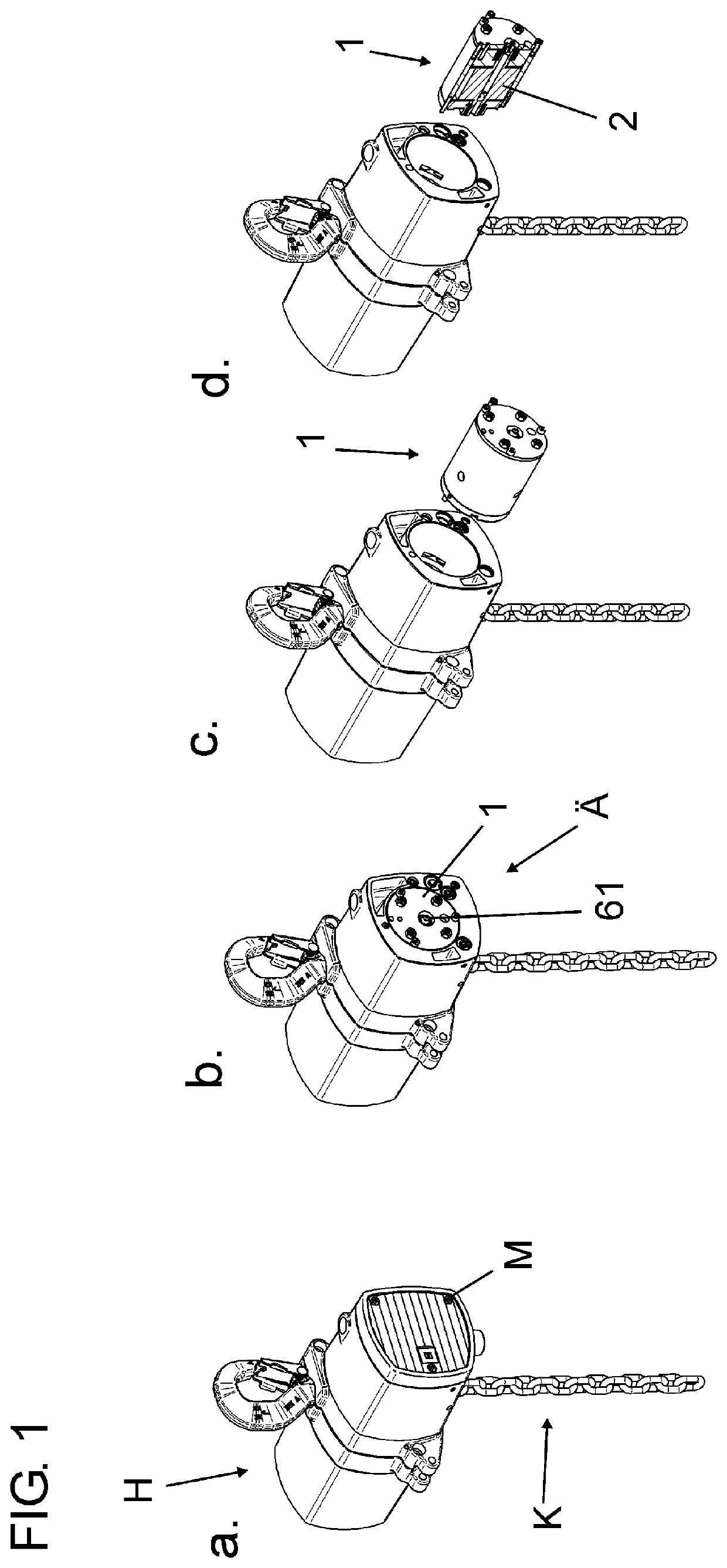
[0039]By means of a hoist H portrayed in FIG. 1, a load on a chain K can be lifted and lowered. To drive the chain K, the hoist H has a vane motor 1 behind a motor cover M as well as additional components. The vane motor 1 has means for lubricating the motor components without the vane motor 1 having to be disassembled. When the motor cover M is removed, a lubrication nipple 61 is accessible from the outside Ä of the vane motor 1 (see FIG. 1b) so that lubrication of the fully assembled vane motor 1 installed in the hoist H is possible.

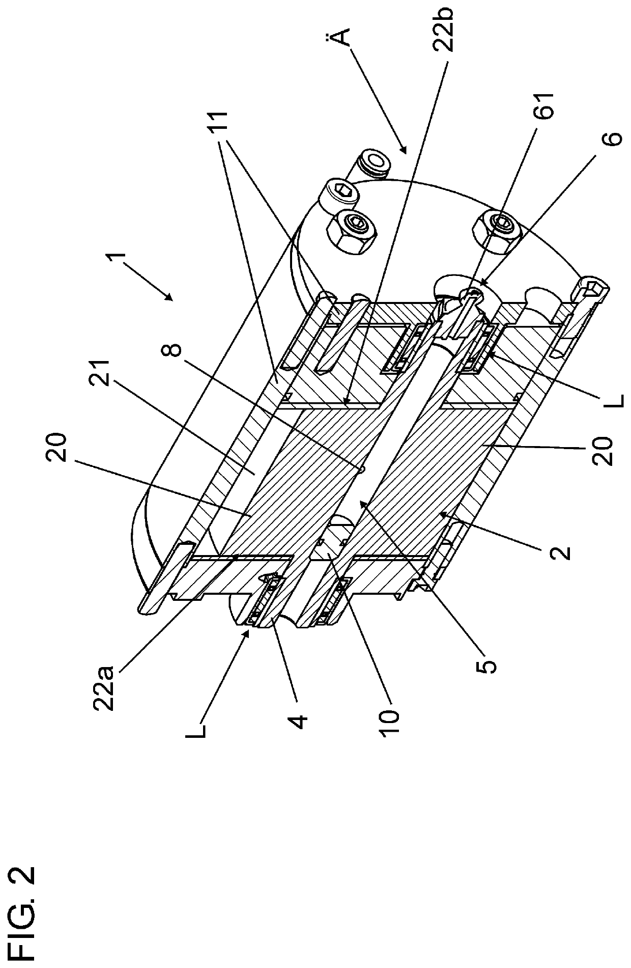
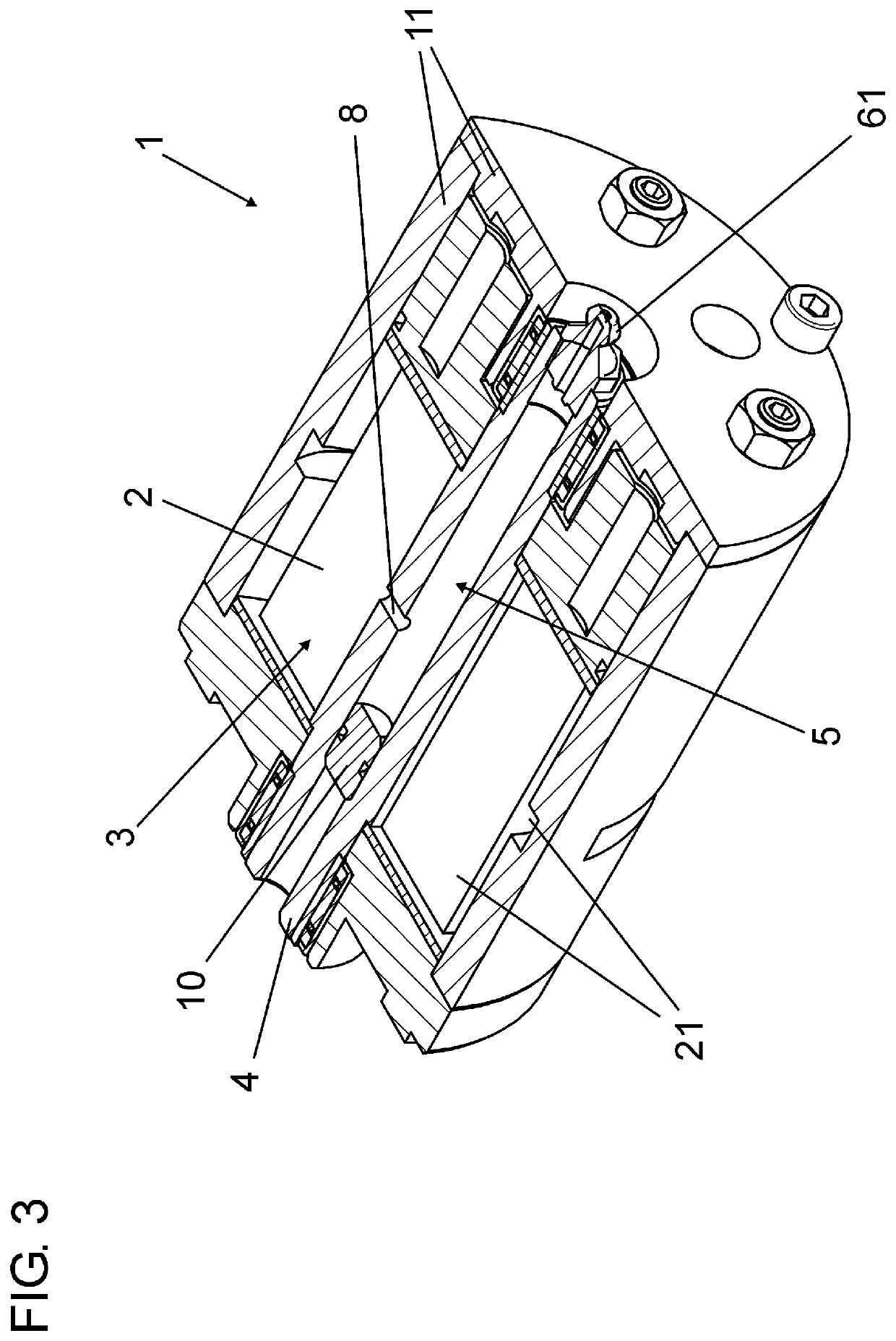
[0040]The vane motor 1 has a rotor body 2 rotatably arranged within a motor bushing 11. In order to enable rotation of the rotor body 2, it is integral with a rotor shaft 4 which is arranged eccentrically in the cylindrical motor bushing 11. Between the rotor shaft 4 and a motor housing, or respectively a part of the motor bushing 11, a bearing L is arranged at both ends of the rotor shaft 4. Moreover, a plurality of vanes are guided in vane gaps 3 of ...


PUM


Abstract

A vane motor with a rotor body driven by compressed air having vane gaps for radially movable vanes and a rotor shaft for rotatably bearing the rotor body relative to a motor bushing. A method for lubricating a vane motor that ensures particularly long, low-service operation is provided. The rotor shaft is configured as a hollow shaft with a first lubricant reservoir in the interior. The first lubricant reservoir has a lubricant filling opening accessible from the outside of the vane motor. The first lubricant reservoir is connected by at least one radial lubricant hole to at least one further lubricant reservoir arranged in a section of the rotor body between two vane gaps, and/or is connected to an outlet opening arranged in one of the vane gaps for supplying lubricant into the vane gap.

Description

CROSS-REFERENCE TO RELATED APPLICATIONS[0001]This application is a U.S. National Stage of International Application No. PCT / EP2019 / 052251, filed Jan. 30, 2019, which claims the benefit of Germany Patent Application No. 10 2018 102 393.6, filed Feb. 2, 2018, both of which are incorporated herein by reference in their entireties.BACKGROUND OF THE INVENTION[0002]The invention relates to a vane motor with a rotor body driven by compressed air with vane gaps for radially movable vanes, and with a rotor shaft for rotatably mounting the rotor body relative to a motor bushing. Moreover, the invention relates to a method for lubricating such a vane motor.[0003]Vane motors are known in various embodiments from the prior art and are used for a wide range of applications, for example as a pneumatic motor for a hoist.[0004]With such a vane motor, a rotor body is arranged eccentrically in a motor bushing. Longitudinal slots, the vane gaps, in which vanes are movably arranged, are in the rotor bod...

Claims


Application Information

Patent Timeline
IPC IPC(8): F03C2/00F03C4/00F04C2/00F01C21/04F01C1/344F04C29/02F04C18/344
CPCF01C21/04F01C1/344F04C18/3442F04C29/023F04C2240/603F01C1/3442F04C2210/1005
Inventor SAWITZKI, EWALDBROSE, SIMON
Owner J D NEUHAUS HLDG
Why Eureka
Try Eureka