Sensor network system managing method, sensor network system managing program, storage medium containing sensor network system managing program, sensor network system managing device, relay network managing method, relay network managing program, storage medium containing relay network managing program, and relay network managing device

a sensor network and management method technology, applied in the field of sensor network systems, can solve the problems of increasing the maintenance workload of the sensor network system manager, running out of battery power, and requiring maintenance work to recharge the sensor, so as to prolong the remaining drive time of the battery, reduce the frequency and maintenance workload, and operate longer

Inactive Publication Date: 2006-09-19
ORMON CORP
View PDF20 Cites 51 Cited by
  • Summary
  • Abstract
  • Description
  • Claims
  • Application Information

AI Technical Summary

Benefits of technology

[0135]As in the foregoing, a sensor network system managing method in accordance with the present invention is implemented by a sensor network system managing device, communicable with sensors, which receives sensor information from the sensors and controls operation of the sensors, and involves the steps of: acquiring remaining drive times of batteries in the sensors; specifying a target remaining drive time; and controlling the operation of the sensors so that the remaining drive times of the batteries in the sensors are substantially equal to the target remaining drive time.
[0136]Another sensor network system managing method in accordance with the present invention may be arranged, in the foregoing method, so that the target remaining drive time is set to the remaining drive time of a battery in a sensor of which the battery has the longest remaining drive time at the time.
[0137]According to the method, the target remaining drive time is set to the remaining drive time of a battery in a sensor of which the battery has the longest remaining drive time; therefore, the operation of the other sensors is controlled so as to extend the remaining drive times of the batteries. The sensors can thus operate longer before they need recharging. Recharge frequency and maintenance workloads are both reduced.
[0138]Another sensor network system managing method in accordance with the present invention may be arranged, in the foregoing method, so that: remaining battery power is detected; a target average power consumption is calculated from the remaining power and the target remaining drive time; and the operation of the sensor is controlled so as to achieve the target average power consumption.
[0139]According to the method, first, the remaining battery power of a sensor is detected. A target average power consumption is calculated from the remaining power and the target remaining drive time. Having determined the target average power consumption in this manner, it is understood how the sensors should be operated to achieve the target remaining drive time. It is therefore appropriately understood how the operation of the sensors should be controlled.
[0140]Another sensor network system managing method in accordance with the present invention may be arranged, in the foregoing method, so that a minimum operation control value at which a minimum level of functions is achieved is specified in advance for each sensor; and the operation of the sensors is controlled so as not to fall below the minimum operation control value.

Problems solved by technology

If one of battery-driven sensors in a system runs out of battery power, a maintenance work is required to recharge the sensor.
The sensors vary in battery capacity and power consumption, therefore running out of battery power at different times from sensor to sensor.
Under these circumstances, the batteries must be frequently recharged, which adds to the maintenance workload for the sensor network system manager.
If the relay is driven by a battery, it quickly consumes battery power and calls for frequent recharging of the battery.
This means added frequency of maintenance recharging and an added workload for the sensor network system manager.
Another problem is that an extremely frequent use of a relay shortens the service life of the relay and its battery.

Method used


Image

  • Sensor network system managing method, sensor network system managing program, storage medium containing sensor network system managing program, sensor network system managing device, relay network managing method, relay network managing program, storage medium containing relay network managing program, and relay network managing device
  • Sensor network system managing method, sensor network system managing program, storage medium containing sensor network system managing program, sensor network system managing device, relay network managing method, relay network managing program, storage medium containing relay network managing program, and relay network managing device
  • Sensor network system managing method, sensor network system managing program, storage medium containing sensor network system managing program, sensor network system managing device, relay network managing method, relay network managing program, storage medium containing relay network managing program, and relay network managing device

Examples


embodiment 1

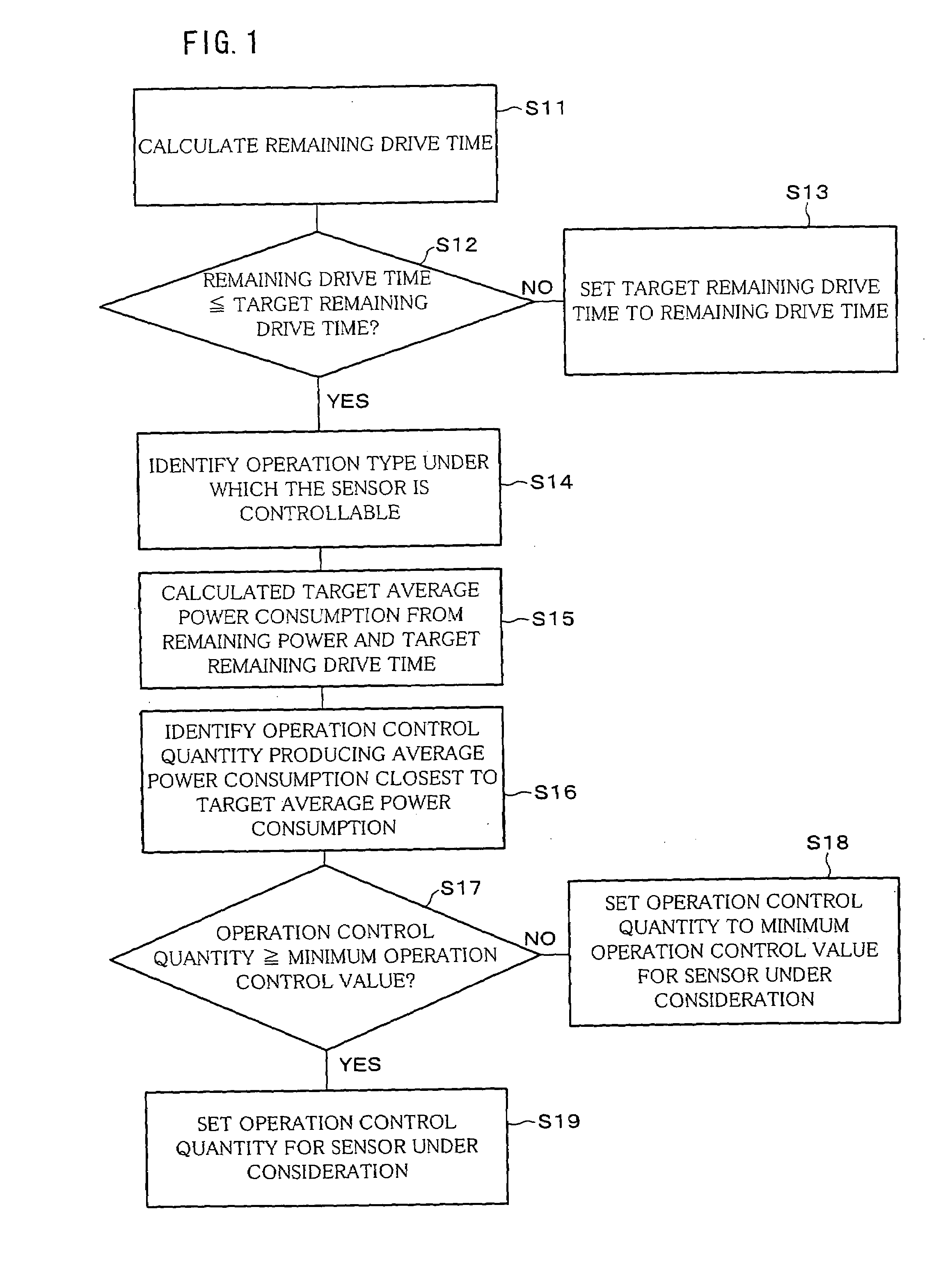
[0033]Referring to FIG. 1 through FIG. 7, the following will describe an embodiment in accordance with the present invention.

(Overall Structure)

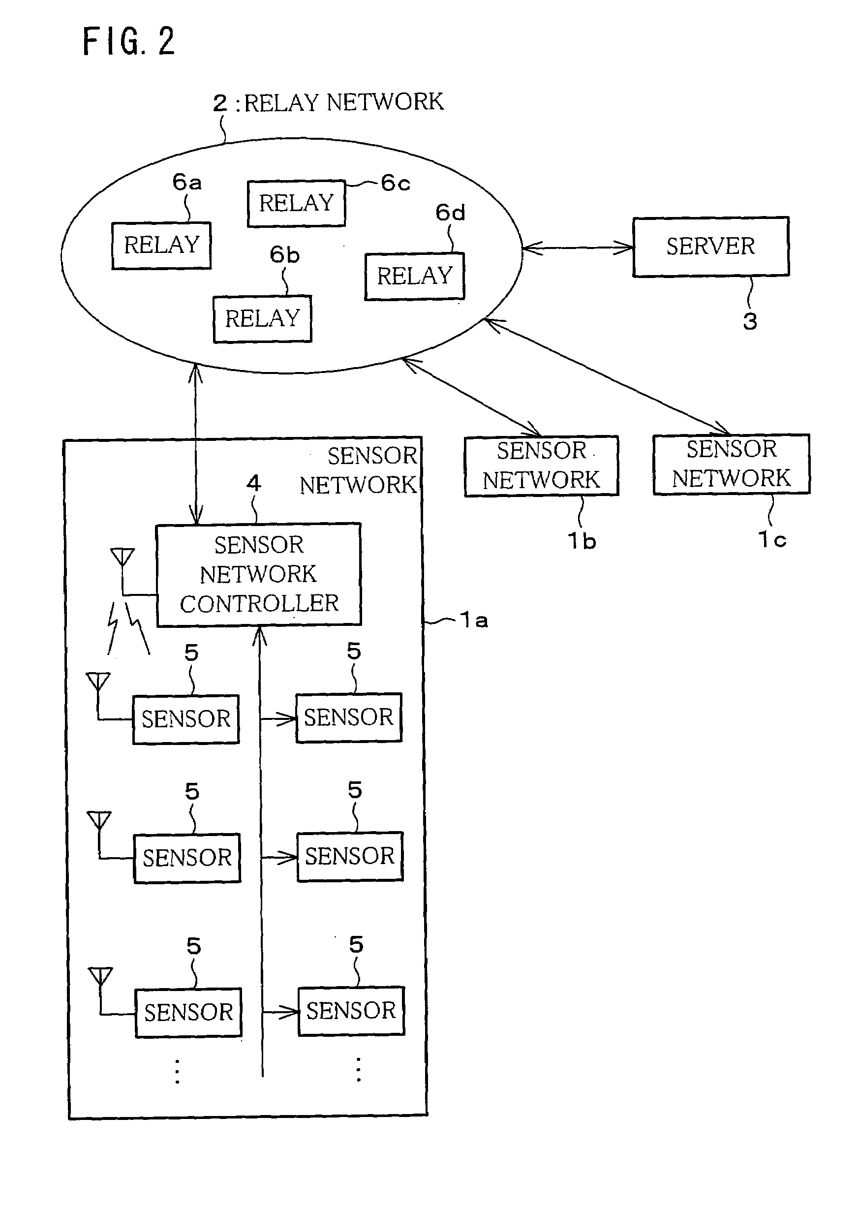
[0034]FIG. 2 is a block diagram schematic illustrating a configuration of a sensor network system in accordance with the present embodiment. The sensor network system includes sensor networks 1a, 1b, 1c, a relay network 2, and a server (sensor network system managing device or relay network managing device) 3.

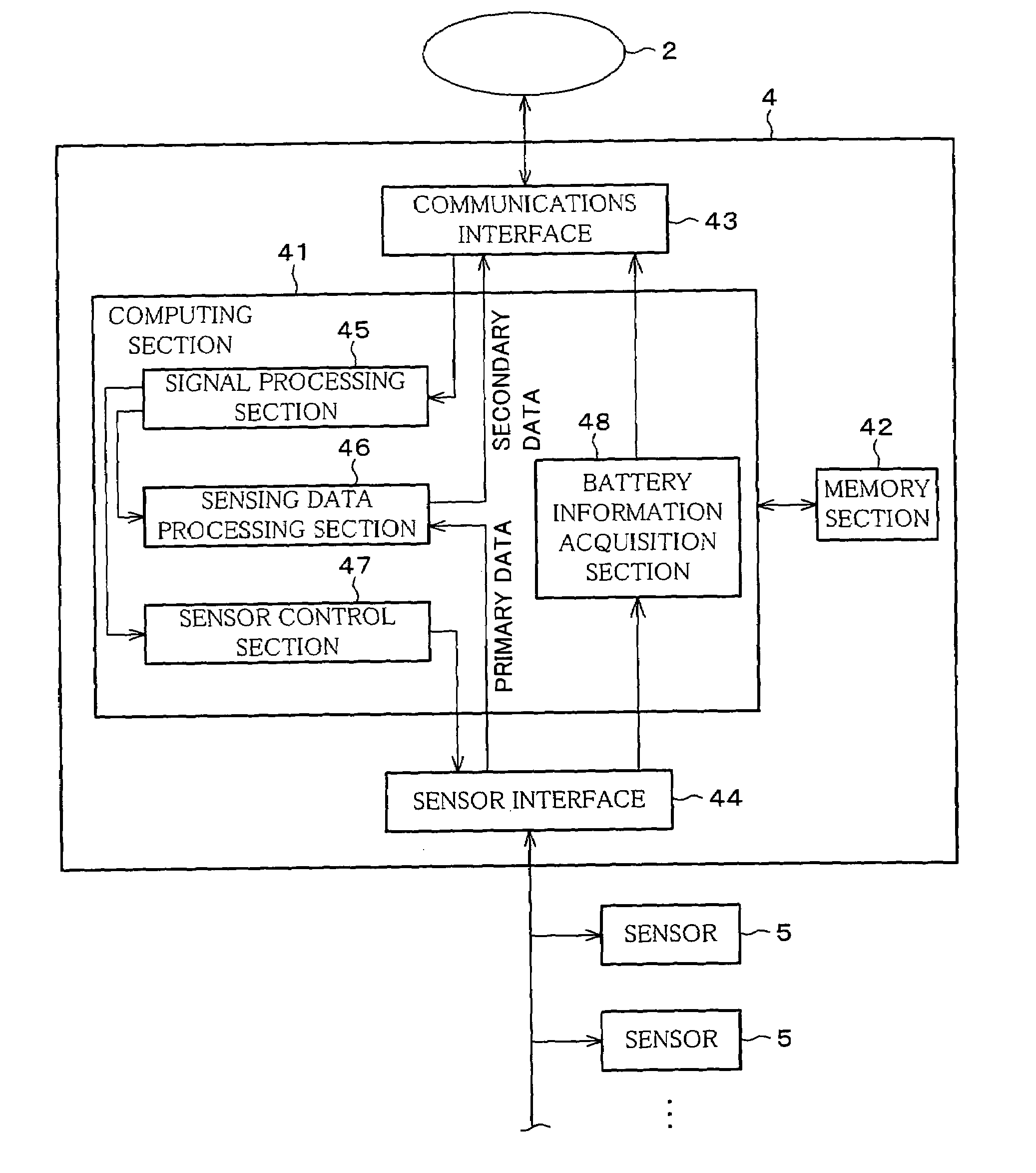
[0035]Each sensor network 1a, 1b, 1c includes a sensor network controller 4 and a set of sensors 5. FIG. 2 depicts an internal structure only for the sensor network 1a; the sensor networks 1b, 1c have a similar structure. In the following, a given one of the sensor networks 1a, 1b, 1c will be referred to as the “sensor network 1” when there is no need to discriminate between the networks 1a, 1b, 1c.

[0036]The relay network 2 includes a set of relays 6a, 6b, 6c, 6d. Each relay is capable of wireless communications with others. Here, as t...

embodiment 2

[0112]The following will describe another embodiment of the present invention in reference to FIG. 8 through FIG. 10. Here, for convenience, members of the present embodiment that have the same arrangement and function as members of embodiment 1, and that are mentioned in that embodiment are indicated by the same reference numerals and description thereof is omitted.

[0113]A sensor network system in accordance with the present embodiment is capable of controlling relay routes in a relay network 2, as well as the functions of the sensor network system in accordance with embodiment 1. The sensor network system in accordance with the present embodiment is arranged similarly to the arrangement described in embodiment 1 with reference to FIG. 2. Differences lie in the configuration of a server 3 which will be detailed later.

[0114]In a sensor network system in accordance with the present embodiment, the relay network 2 is composed of a set of relays 6, working as a relay enabling data tran...


PUM


Abstract

In a sensor network system, a communications network connects a set of sensors to a server collectively managing the set of sensors. First, the sensor-managing server acquires remaining drive times of batteries in the sensors, and specifies a target remaining drive time. The server then controls the operation of the sensors so that the remaining drive times of the batteries in the sensors are substantially equal to the target remaining drive time. This reduces the maintenance workload for a system manager, especially, in the recharging of the sensor batteries.

Description

TECHNICAL FIELD[0001]The present invention relates to sensor network systems in which multiple sensors are connected over a communications network to a server collectively managing the sensors.BACKGROUND ART[0002]A huge variety of sensors have been used in large numbers in our everyday life for some time. They are specialized for particular purposes including detection of car thefts, house break-ins, and fires. These sensors typically make up sensor networks for individual purposes. A sensor network system made up of these sensor networks is capable of collectively managing various kinds of sensor information.[0003]Each sensor network has a sensor network controller connected to the sensors by a wired or wireless communicable link. Therefore, results of detection by sensors and other sensor information are communicated by the sensor network controller.[0004]In addition, the sensor network system has a server computer (“server”) which collectively manages information from the sensor ...

Claims


Application Information

Patent Timeline
Patent Type & Authority Patents(United States)
IPC IPC(8): G08B21/00G08B25/00G08B25/01G08B25/10G08B29/18G08C17/00H04B7/15H04B7/26H04L12/28H04M3/00H04Q9/00
CPCG08B25/009G08B29/181G08B25/10
Inventor OTA, SHUNJIOTSUKI, YOSHIYUKIOYAGI, MASAYUKIYAMATO, MASAKI
Owner ORMON CORP
Why Eureka
Try Eureka