

Fuel cell, electronic appliance and business method
- Summary
- Abstract
- Description
- Claims
- Application Information
AI Technical Summary
Benefits of technology
Problems solved by technology
Method used
Image

Examples
embodiment 1
[0052] (Embodiment 1)
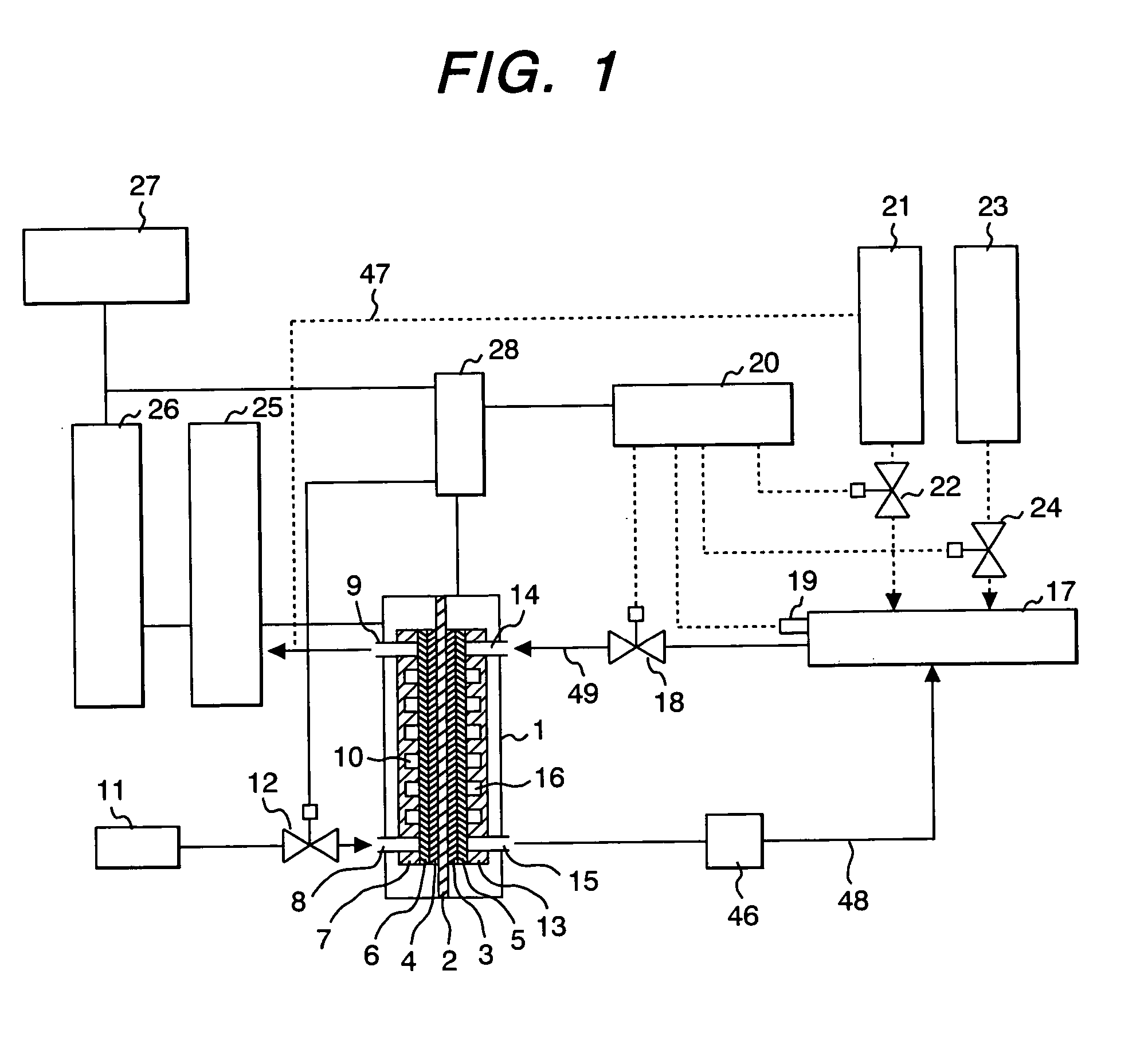
[0053]FIG. 1 shows a diagrammatic view of a fuel cell system which employs a methanol fuel cell (DMFC) for a personal computer. The fuel cell of this embodiment comprises an electrolyte / electrode assembly (MEA), which is constituted by an anode catalyst layer 3 and a cathode catalyst layer 4 and a polymer electrolyte membrane 2 sandwiched by the catalyst layers, an anode collector 5 at the anode side, a cathode collector 6 at the cathode side, each being closely contacted. An air flow plate 7 is disposed at the cathode collector 6 side, the air flow plate 7 being provided with an air flow passage having an air supply port 8 and an air discharging port 9.
[0054] The air flow passage 10 is connected to an oxidant supply means including a blower or a fan for supplying air 11 containing oxygen. At the same time, water produced by reduction reaction of oxygen at the cathode is discharged from the air discharging port 9. The recovered water is stored in the produced w...
embodiment 2
[0071] (Embodiment 2)
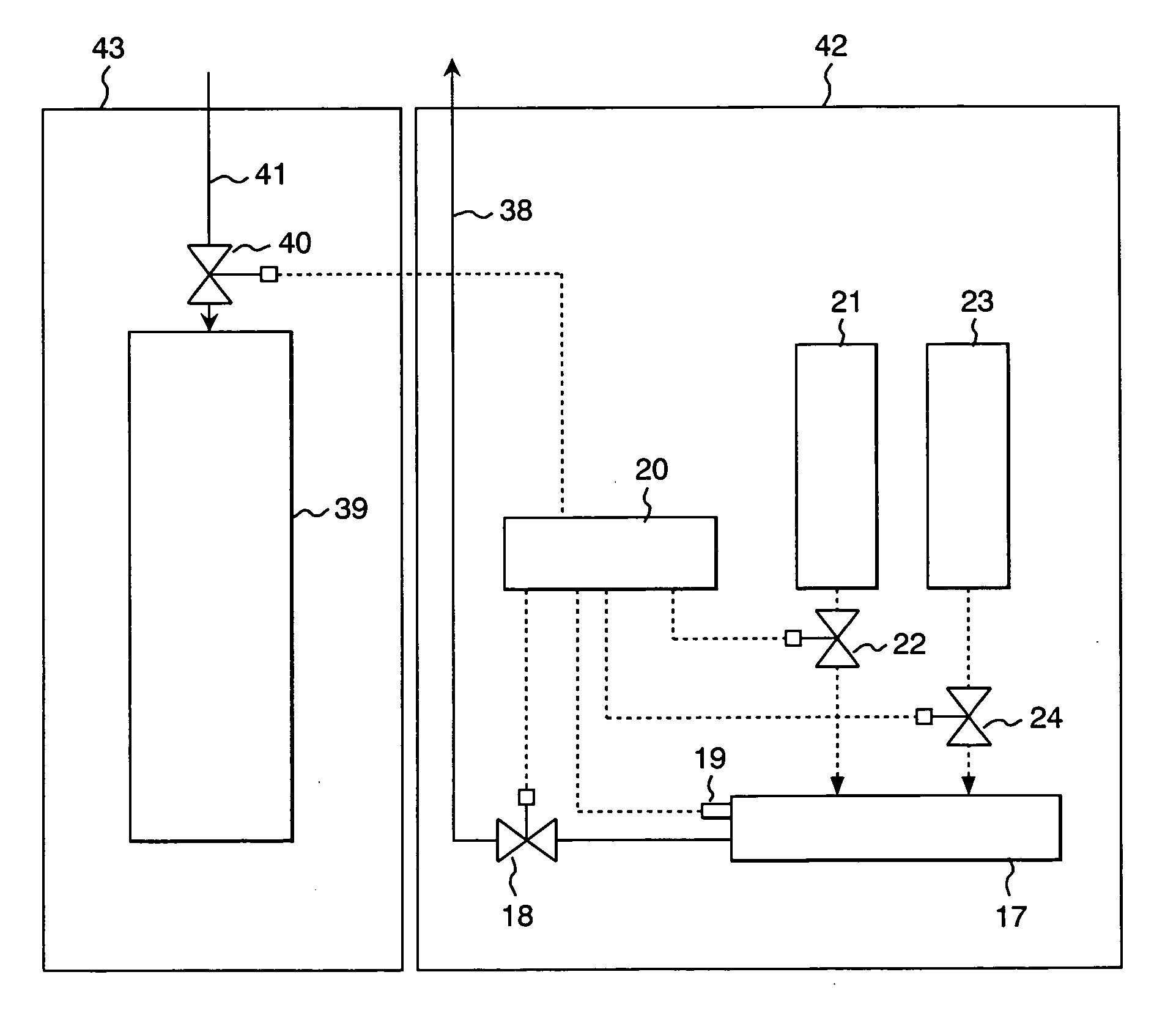
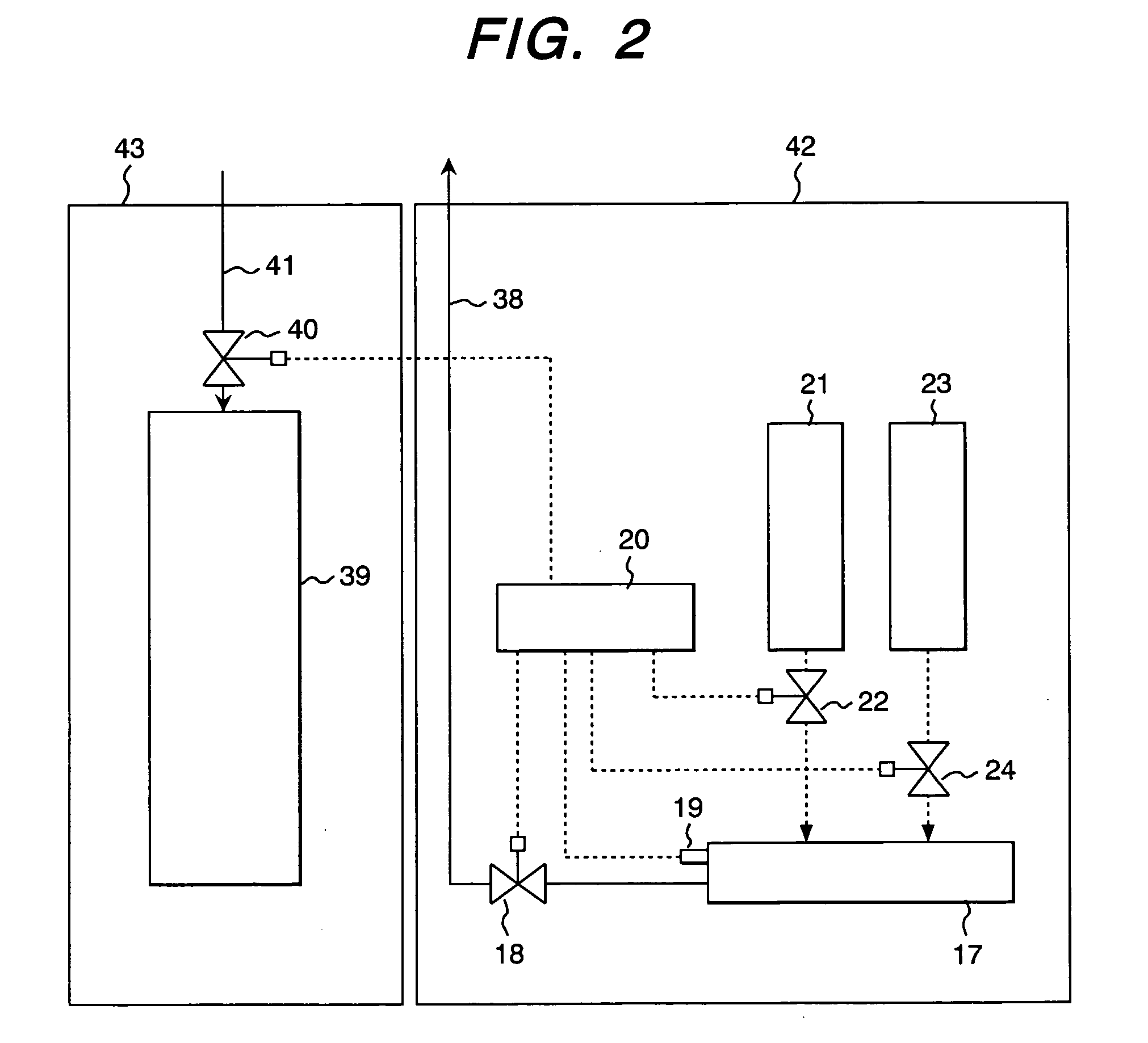
[0072]FIG. 2 shows a diagram of a fuel recovery—supply apparatus, which carries out fuel recovery and fuel supply, simultaneously. The fuel recovery—supply apparatuses are installed at convenience stores, railway kiosks, hotels, coffee shops, etc. for recovering used fuel that contains ionic impurities, etc. and supplying fresh liquid fuel upon requests of users of personal computers, PDAs', portable telephones, etc. that are equipped with fuel cells. As explained in the embodiment shown in FIG. 1, liquid fuel solution in the fuel solution container 17 accumulates ionic impurities as the operation time lapse to thereby lower the output, resulting in its short life span, since the liquid fuel circulates through the container 17 and the fuel cell.
[0073] The concentration of the ionic impurities in the used liquid fuel in the liquid fuel solution container 17 is detected. When the concentration exceeds the predetermined value, the liquid fuel is recovered and repl...
embodiment 3
[0079] (Embodiment 3)
[0080]FIG. 3 shows a perspective view of a personal computer that employed the fuel cell system according to the present invention. This embodiment is concerned with a personal computer wherein a panel type fuel cell power source section 29 is accommodated in a liquid display. Slits in the surface of the power source shown in FIG. 3 are air intake ports 45. As shown by dotted lines at hinges, the fuel circulating tank 30 for methanol solution of a predetermined concentration and methanol fuel tank 31 are held on the holder means 44.
[0081] Methanol fuel is supplied to the liquid fuel solution circulating tank 30 from the methanol fuel tank 31 successively. If the output of the fuel cell gets down to less than 80% of the rated output at the time that fuel is supplied to the liquid fuel tank 31 from the fuel charger, the fuel circulating tank 30 that has been used is replaced with a new one. If the replacement is repeated, the service life of the fuel cell will be...
PUM
 Abstract
Description
Claims
Application Information