
Power apparatus and electronic equipment

Inactive Publication Date: 2005-07-28
NEC CORP
View PDF12 Cites 51 Cited by
  • Summary
  • Abstract
  • Description
  • Claims
  • Application Information

AI Technical Summary

Benefits of technology

[0010] It is an object of the present invention to provide a power apparatus and an electronic equipment which can supply power even when an outside battery is detached from the main body of the electronic equipment. It is also an object of the present invention to provide a compact power apparatus and an electronic equipment which can keep the electronic equipment operating over a long time period.
[0015] In the present invention, since the second and the third detecting means detect the voltages of the first battery and the second battery respectively, a determining means switches, during the use of the electronic equipment, the battery for use as the power supply based on the results of detection according to the above-mentioned battery voltages. Therefore, the electronic equipment remains usable over a long time period, because both batteries can be used up until the remaining battery level runs out. In addition, as the second battery, a small capacity battery, i.e. that having a smaller volume is available, therefore, miniaturization or slimming of electronic equipments can be realized, and also enhancing design flexibility in terms of appearance can be performed.

Problems solved by technology

Since portable electronic equipments such as cellular phones use batteries as the power apparatus, the cellular phones become unusable when the remaining battery level runs out.
Enhancement of the above-mentioned cellular phone functionalities increases power consumption.
However, power supply from the battery pack to the control circuit (battery switching circuit) stops when the battery pack is suddenly detached from the cellular phone during the use of the battery pack.
However, the patent literature 2 lacks disclosure of a concrete arrangement for switching from the external battery to the internal battery when the external battery is detached, hence preventing implementation as a product.
In other words, the above-mentioned software design alone may not practically avoid turning off the power before switching from the external battery to the internal battery, when the external battery is detached.

Method used


Image

  • Power apparatus and electronic equipment
  • Power apparatus and electronic equipment
  • Power apparatus and electronic equipment

Examples


Embodiment Construction

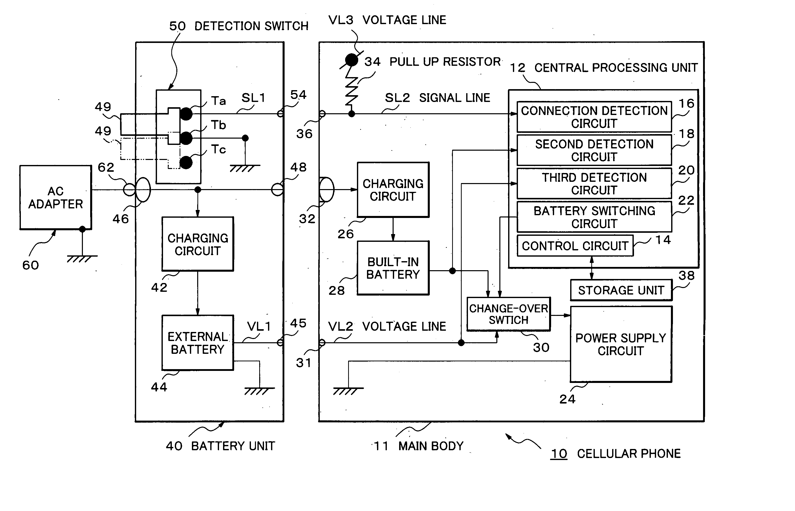
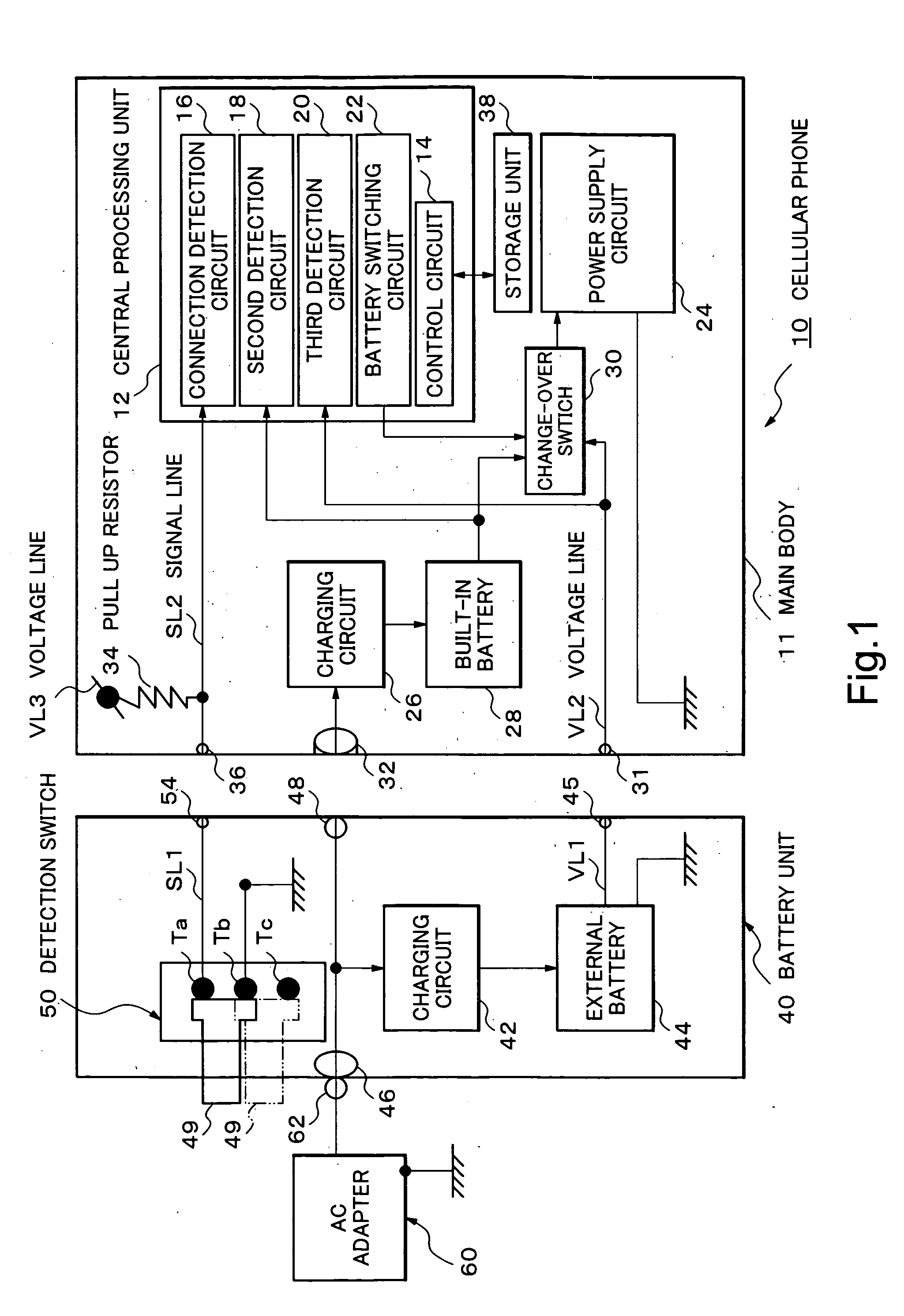
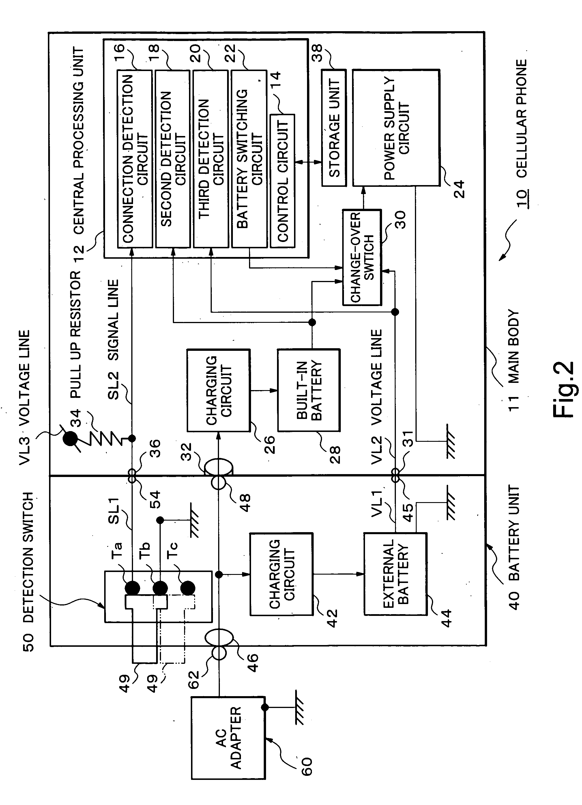
[0022] A power apparatus and an electronic equipment such as a cellular phone, composing an embodiment of the present invention, will be described based on FIGS. 1 and 2, as follows.

[0023] (General Arrangement with Regard to the Power Line of a Cellular Phone)

[0024] Referring to FIG. 1, an arrangement of the power line with regard to a cellular phone is described. A main body (housing) 11 of a cellular phone 10 and a battery unit 40 are arranged in a detachable coupling (connection). For example, the battery unit 40 can be attached to or detached from the main body 11 by sliding the battery unit 40 relative to the main body 11. Here, the cellular phone 10 comprises a central processing unit (CPU) 12, a power supply circuit 24, a first charging circuit 26, a built-in battery 28 that is a first battery, a change-over switch 30 and a connecting terminal 32.

[0025] On the other hand, the battery unit 40 and an AC adapter 60 are arranged to be connectable. Here, since the AC adapter 60...


PUM


Abstract

A lock key is unlocked in a state where a cellular phone is processing a call and using an external battery as the power supply. A “HIGH” signal is inputted to a connection detection circuit before the power supply from the external battery stops. A control circuit determines, based on the voltage detected by the connection detection circuit, that a battery unit in which the external battery is disposed and the main body of the cellular phone are in a detaching-state, and switches the power supply from the external battery to a built-in battery of the cellular phone via a battery change-over circuit. In other words, because the switching process of the power supply takes place in the above-mentioned detaching-state after unlocking the lock key, the power supply to the cellular phone is not interrupted, and the power-on state is kept, and the call, etc. are continued.

Description

BACKGROUND OF THE INVENTION [0001] 1. Field of the Invention [0002] The present invention relates to a power apparatus which attaches or detaches a battery unit to or from the main body of a cellular phone and an electronic equipment using a power apparatus. Specifically, the present invention relates to a power apparatus which supplies electric power by switching, for example, a second battery connected externally to a cellular phone and a first battery disposed inside the main body of the cellular phone, and an electronic equipment using a power apparatus. [0003] 2. Description of the Related Art [0004] Since portable electronic equipments such as cellular phones use batteries as the power apparatus, the cellular phones become unusable when the remaining battery level runs out. Therefore, some types of cellular phones have been proposed, wherein a plurality of batteries are provided and the battery voltage is monitored so as to give out an alarm (warning message) when the remainin...

Claims


Application Information

Patent Timeline
IPC IPC(8): H02J7/00H02J7/02H02J9/06H04B7/26
CPCH02J9/061Y02D30/70
Inventor NAGASAWA, MAKOTO
Owner NEC CORP
Learn More