Voltage equalization control system of accumulator

a voltage equalization and control system technology, applied in the direction of charge equalization circuit, transportation and packaging, battery arrangement for several simultaneous batteries, etc., can solve the problem of affecting the loss of energy transfer between the cells at a voltage equalization reaches such a high level, and the difference of voltage in each cell. to achieve the effect of maintaining the performance of the assembled battery and reducing the remaining energy

Inactive Publication Date: 2006-06-08
FUJI JUKOGYO KK
View PDF18 Cites 51 Cited by
  • Summary
  • Abstract
  • Description
  • Claims
  • Application Information

AI Technical Summary

Benefits of technology

[0010] One or more embodiments of the present invention provide a voltage equalization control system of accumulator which can moderate a decrease of the remaining energy i

Problems solved by technology

However, there occurs a difference of voltage in each cell owing to a difference in its capacitance and internal resistance through the repetition of charge/discharge.
So, there is a possibility of deteriorating the cells because excessive voltage and inversion of polarity occur in the respective cells.
When a voltage difference between cells is comparatively large and it takes a long time to do the voltage equalizing processing

Method used


Image

  • Voltage equalization control system of accumulator
  • Voltage equalization control system of accumulator
  • Voltage equalization control system of accumulator

Examples


first embodiment

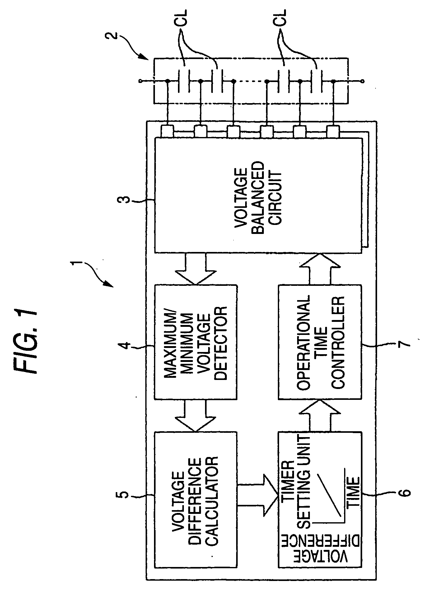
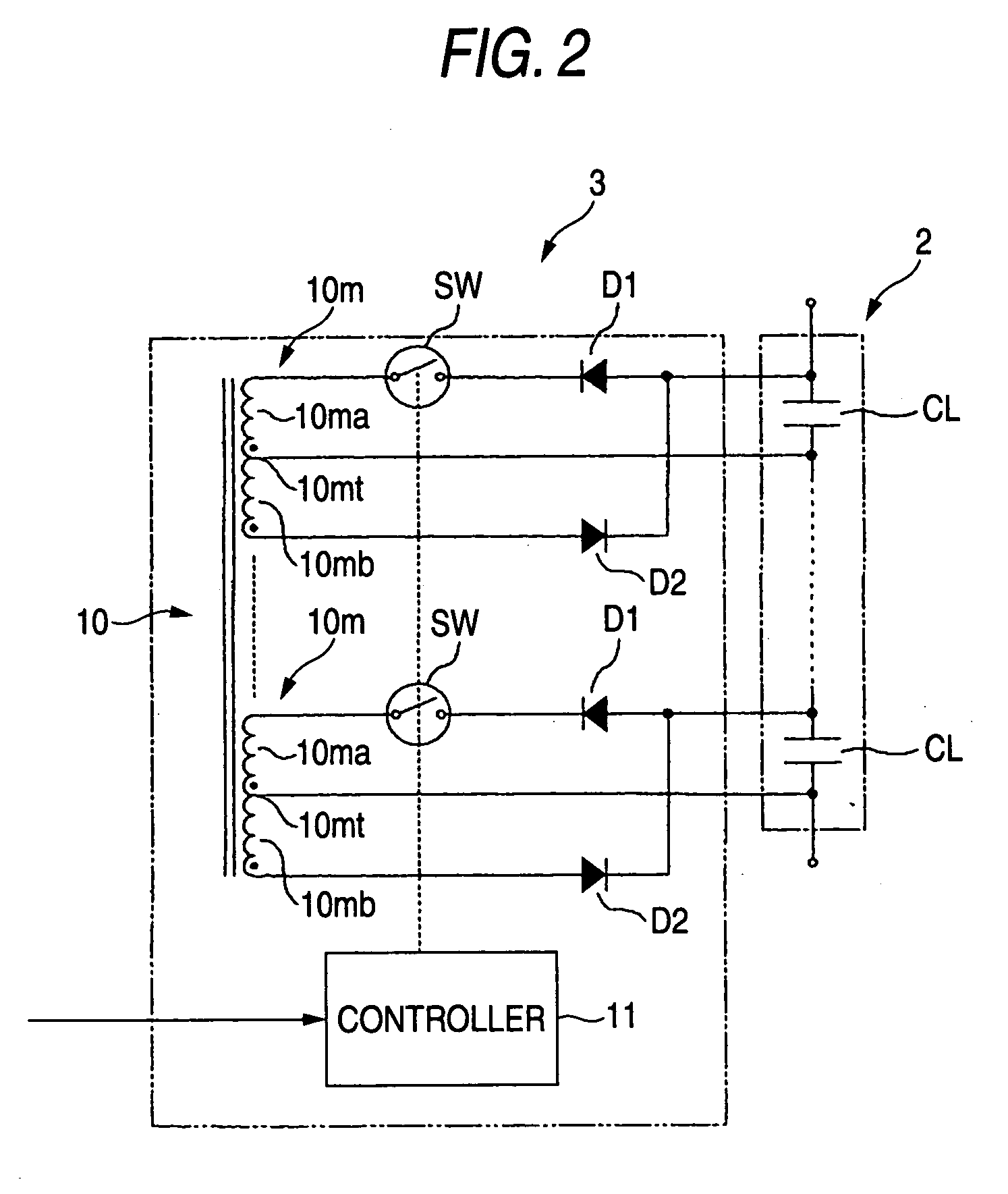
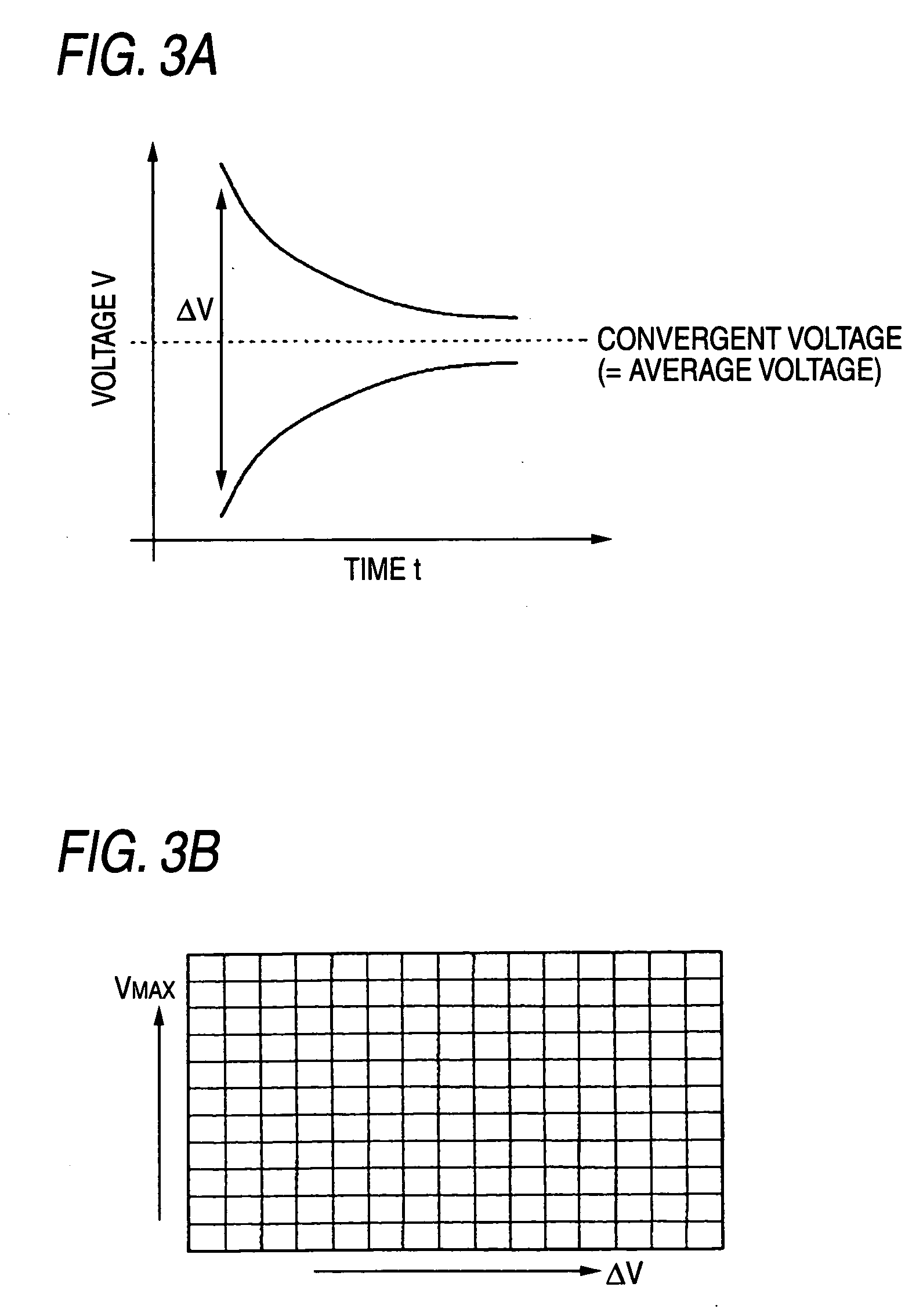
[0026] FIGS. 1 to 4 are concerned about the invention: FIG. 1 is a structural view of a voltage equalization control system; FIG. 2 is a circuit diagram of a voltage balanced circuit; FIG. 3A is an explanatory view of the timer selection map based on a voltage difference; FIG. 3B is an explanatory view of the timer selection map based on the maximum terminal voltage and the voltage difference; and FIG. 4 is an explanatory view showing the expanded function of the voltage equalization control system.

[0027] The voltage equalization control system 1 shown in FIG. 1 is mainly applied to a power source of low voltage mechanism (for example, 12V battery of a vehicle) and intended to an assembled battery 2 which is used as the power source of low voltage mechanism with the comparatively small number of accumulators CL, . . . connected in series. In the embodiment, an accumulator CL is assumed to be, for example, a rechargeable lithium-ion battery or an electric double layer capacitor. A si...

second embodiment

[0058]FIGS. 5 and 6 are concerned about the invention: FIG. 5 is a structural view of the voltage equalization control system and FIG. 6 is a circuit diagram of the voltage balanced circuit.

[0059] The second embodiment is applied to the case where a plurality of accumulators CL, . . . are connected in series a lot, hence to form a power source of high voltage mechanism, like a battery for a hybrid car or an electric vehicle.

[0060] As illustrated in FIG. 5, in the second embodiment, a voltage equalization control system 100 in which a microcomputer 50 is provided as a main part to control an assembled battery 20 including a plurality of battery modules 20a connected in series, each of the battery modules 20a having the comparatively small number of the accumulators CL, . . . connected in series, which battery module corresponds to the assembled battery 2 of the first embodiment, performs the voltage equalization control on the accumulators CL, . . . in every battery module 20a.

[006...


PUM


Abstract

A maximum/minimum voltage detector detects a maximum terminal voltage and a minimum terminal voltage of a plurality of accumulators. A voltage difference calculator calculates a voltage difference between the maximum terminal voltage and the minimum terminal voltage. A timer setting unit sets an operational time of a timer according to the voltage difference. An operational time controller presets the operational time in the timer to temporally control the operation of the voltage balanced circuit. Accordingly, an unnecessary loss of energy due to the long time operation of the voltage balance circuit is prevented, and a performance of the assembled battery is maintained.

Description

CROSS REFERENCE TO RELATED APPLICATIONS [0001] The present application claims foreign priority based on Japanese Patent Application No. P.2004-355299, filed on Dec. 8, 2004, the contents of which are incorporated herein by reference. BACKGROUND OF THE INVENTION [0002] 1. Field of the Invention [0003] The invention relates to a voltage equalization control system of accumulator that equalizes voltages in a plurality of accumulators forming an assembled battery. [0004] 2. Related Art [0005] There is a compact accumulator of high energy density, such as a rechargeable lithium-ion battery and an electric double layer capacitor. It is regarded as a dominant power source of, for example, an electric vehicle run by motor or a hybrid car run by combination of engine and motor. In the accumulator, a desired voltage can be obtained by forming an assembled battery with a plurality of cells connected in series. However, there occurs a difference of voltage in each cell owing to a difference in ...

Claims


Application Information

Patent Timeline
IPC IPC(8): H02J7/00H02J7/02
CPCH02J7/0016Y02T10/7055Y02T10/70
Inventor SAKURAI, MASATOANZAWA, SEIICHIKOBAYASHI, KATSUMI
Owner FUJI JUKOGYO KK
Why Eureka
Try Eureka