
Device and method for transmitting reference signal in multi-antenna system

a reference signal and multi-antenna technology, applied in the field of wireless communication, can solve the problems of increasing the overhead of a control signal, no method of minimizing the overhead of a control, increasing the number of transmission antennas, etc., and achieve the effect of reducing the overhead and minimizing the overhead

Active Publication Date: 2015-10-08
PANTECH CORP
View PDF11 Cites 70 Cited by
  • Summary
  • Abstract
  • Description
  • Claims
  • Application Information

AI Technical Summary

Benefits of technology

The patent text describes a way to reduce the cost and complexity of transmitting data in the next generation mobile communication system. By using a special technique, the system can achieve better performance with fewer resources. This allows for beamforming in a specific direction with minimal overhead. Overall, the patent aims to improve efficiency and performance while reducing costs.

Problems solved by technology

However, if 64 transmission antennas are stably supported, overhead of a control signal is increased.
However, there is no methods for minimizing overhead of a control in addition to increase in the number of transmission antennas.

Method used


Image

  • Device and method for transmitting reference signal in multi-antenna system
  • Device and method for transmitting reference signal in multi-antenna system
  • Device and method for transmitting reference signal in multi-antenna system

Examples


first embodiment

[0115]A first embodiment indicates a differential value with respect to the horizontal change in the beam direction as the information field as listed in the table 10, and includes to report the periodic feedback to the base station.

TABLE 10Code pointsDifferential values0π / 32 increase1π / 32 reduction

second embodiment

[0116]The second embodiment includes wherein the UE uses feedback of another bit with respect to another link. In this case, the maximum number of bits for the periodic feedback is 9 bits. In this case, the maximum 8 bits indicate a differential value with respect to the horizontal change in the beam direction and a remaining one bit indicates a differential value with respect to the vertical change in the beam direction.

[0117]For example, if the rank is greater than 4, one bit with respect to each layer is used to indicate a differential value with respect to the horizontal change in the beam direction. If the rank is 3 or 4, two bits with respect to each layer are used to indicate a differential value with respect to the horizontal change in the beam direction. If the rank is 1 or 2, four bits with respect to each layer are used to indicate a differential value with respect to the horizontal change in the beam direction. This is expressed by a following table 11.

TABLE 11RanksThe b...


PUM


Abstract

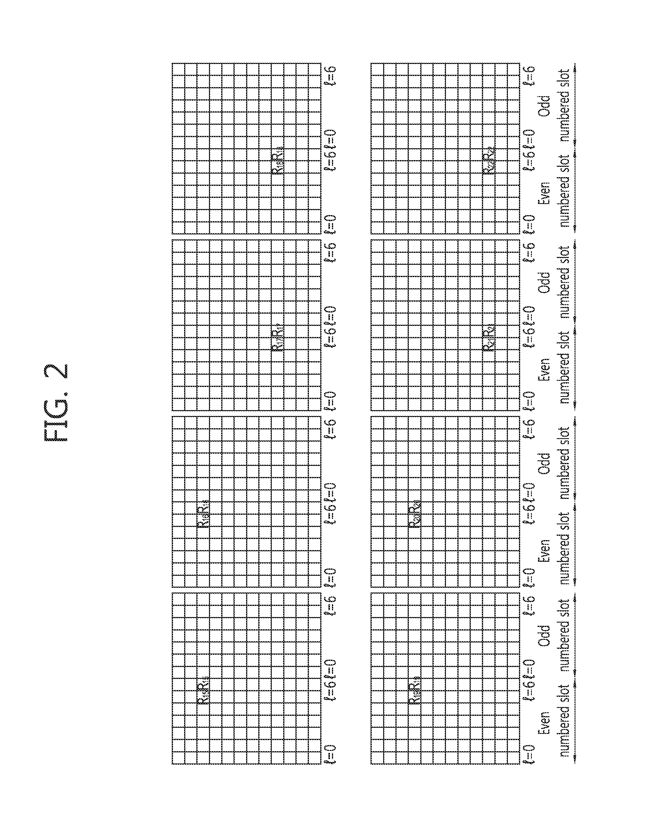
The present invention relates to a device and a method for transmitting a reference signal in a multi-antenna system. The present specification discloses a method for receiving a reference signal, the method comprising the steps of: receiving, from a base station, first channel state information (CSI) reference signal (CSI-RS) configuration information including individual parameters necessary when a terminal receives a first CSI-RS from a horizontally adjacent horizontal representative antenna among the all of the transmission antennas of the base station and second CSI-RS configuration information including individual parameters necessary when the terminal receives a second CSI-RS from a vertically adjacent vertical representative antenna; and receiving the respective first and second CSI-RSs from the base station on the basis of the first CSI-RS configuration information and the second CSI-RS configuration information.

Description

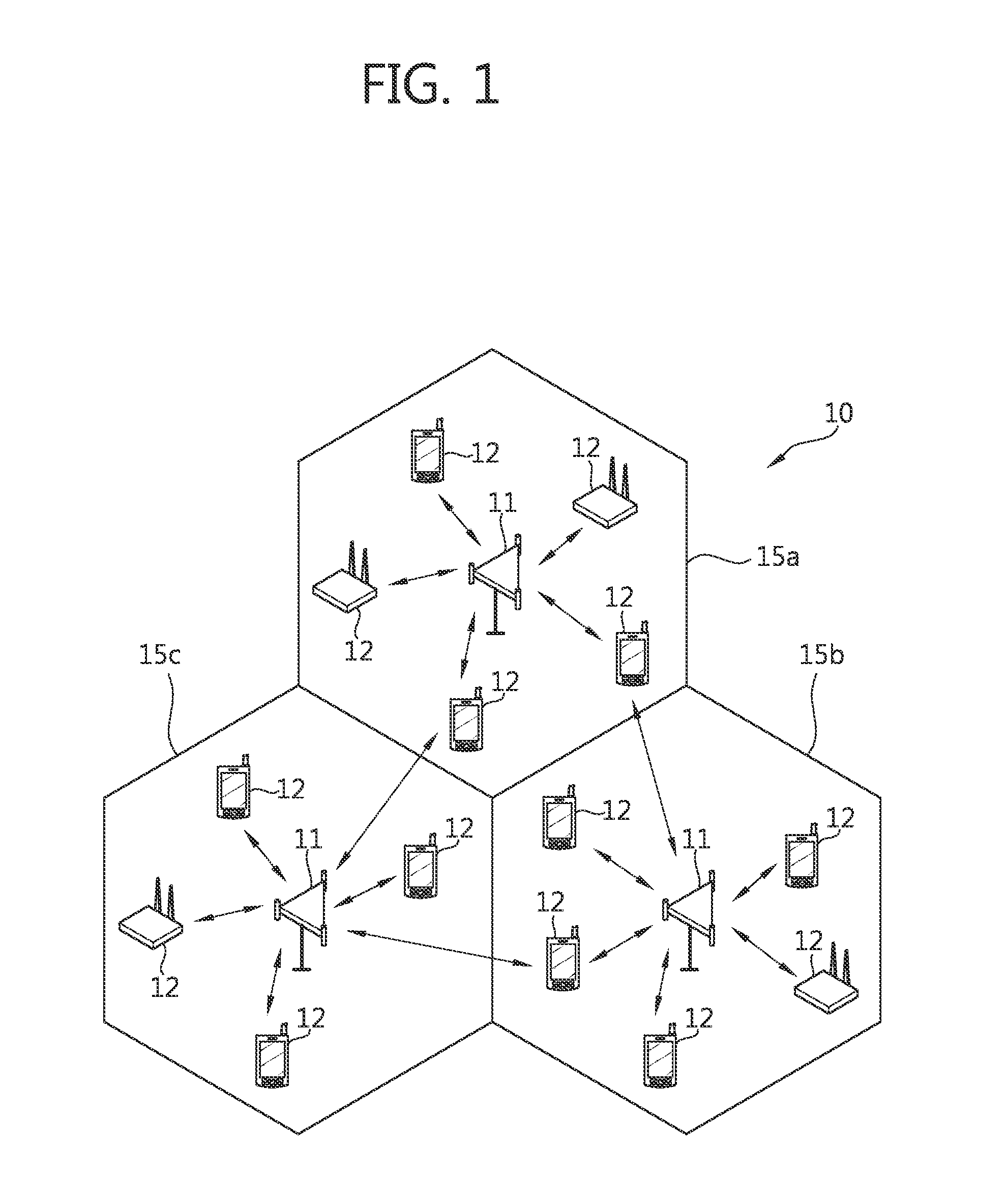
CROSS-REFERENCE TO RELATED APPLICATIONS[0001]This application is the National Stage Entry of International Application PCT / KR2013 / 009299, filed on Oct. 17, 2013, and claims priority from and the benefit of Korean Patent Application No. 10-2012-0123583, filed on Nov. 2, 2012, both of which are incorporated herein by reference for all purposes as if fully set forth herein.BACKGROUND[0002]1. Field[0003]The present invention relates to wireless communication, and more particularly, to an apparatus and a method for transmitting a reference signal in a multiple antenna system.[0004]2. Discussion of the Background[0005]An existing mobile communication system may support 8 transmission antennas for a beamforming operation. Particularly, in a multi-user Multiple Input Multiple Output (MIMO) operation, the same physical resource block (PRB) may be scheduled or assigned to maximum 4 user equipment (UE). Associated with a configuration of an antenna in a next generation mobile communication sys...

Claims


Application Information

Patent Timeline
Patent Type & Authority Applications(United States)
IPC IPC(8): H04L5/00H04B7/06H04B7/04
CPCH04L5/0048H04B7/0413H04W88/02H04W88/08H04B7/0639H04B7/0478H04B7/0647H04L5/0023H04L5/0094H04B7/0479H04B7/0617H04L25/0224
Inventor LI, JIAN JUNPARK, KYOUNG MIN
Owner PANTECH CORP
Learn More