Optimal link scheduling for multiple links

a technology of multiple link scheduling and link scheduling, applied in the field of communication networks, can solve the problems of packet loss, number of failures in communication links, and too high data packet rate of paths, and achieve the effect of increasing the efficiency of a group of multiple concurrent links

Inactive Publication Date: 2005-03-01
IBM CORP
View PDF26 Cites 73 Cited by
  • Summary
  • Abstract
  • Description
  • Claims
  • Application Information

AI Technical Summary

Benefits of technology

In view of the above discussion, it is an object of the present invention to provide improved flow control through multiple concurrent links in a network.
A further object of the present invention is to account for non-congestion based losses in networks having concurrent multiple links between nodes.
Yet another object of the present invention is to increase the efficiency of a group of multiple concurrent links in a network path when losses of packets on a link in the group of multiple concurrent links occurs.
Another object of the present invention is to reduce the impact on the efficiency of functional links in a group of multiple concurrent links resulting from packet losses on one of the links.
In these threshold embodiments of the present invention, the rate at which packets are provided to a link of the multiple links is based upon whether the transmission quality of the link is above or below a threshold. By decreasing the rate at which packets are provided to individual links as those links performance degrades, retry timeouts may be avoided and performance of the multiple links may be maintained. Furthermore, by providing no or only a few packets to a link if the link has too high an error rate the impact on the other links in the group of a links errors may be reduced.
By scheduling packets to links based upon the smallest delay factor the scheduler may reduce the impact of a link becoming a “lossy” link by reducing the rate at which packets are sent to that link. Furthermore, because the delay factors are calculated dynamically they automatically compensate for changes in loss rates for the links. Thus, a link which becomes lossy may recover and be useable at a later time. Also, by providing for a continuous compensation, rather than threshold oriented compensation, for loss in a link there is no need to set threshold values which may be incorrectly established.

Problems solved by technology

One error condition which many networks attempt to correct for is packet loss.
Congestion may result from too high a data packet rate for a path.
Bit error may, however, result from any number of failures in a communication link.
For example, sun spots may adversely impact microwave transmissions and cause loss of data.
However, bit error occurrences are generally highly correlated.
As a result, a time averaged bit error rate (BER) alone may not accurately describe line quality.
Thus, like many forms of networking, in RTP packet losses are assumed to result from congestion rather than bit errors.
However, these loss rates may not apply to all communication links around the world or even to high quality links all the time.
Furthermore, as RTP provides end-to-end flow control, the send rate of packets on a path may be limited by the slowest link in the path (i.e., the bottle-neck link).
Thus, a congestion problem or the presence of one low speed link in a path may degrade the throughput for the entire path.
One drawback of an MLTG is that packets flowing over an MLTG can arrive at the RTP endpoint out of sequence.
If an MLTG is not in the path, any data received that is out of sequence causes error recovery (i.e., the receiver sends a gap detect message to the sender).
If an MLTG is in the path, error recovery is delayed.
This approach, however, does not take into account the possibility of differing link rates as well as possible congestion on a link or bit errors on a link in the MLTG.
Furthermore, if loss occurs on one of the sublinks, there is no mechanism to account for the change in throughput of the sublink.
This inefficiency follows from each packet loss resulting in a send_rate reduction of 50% to both links in the MLTG.
Inaccuracy in weighting may be a significant problem given the number of multiprotocol link and subnet technologies (e.g., PPP, X.25, multiprotocol encapsulation over frame relay, multiprotocol encapsulation over ATM AAL5), it may be impossible to know the exact throughput available to a particular protocol over a multiprotocol link layer.
Consequently, it may be impossible to know the correct weight values that should be assigned to each sublink.
However, such error recovery may provide minimal improvement over the simple weighted round-robin method.
By the time it is learned that a sublink is in recovery, it is too late.
Also, when operating over a lossy sublink, the link may toggle in and out of error recovery frequently.
However, the throughput of the MLTG still falls below that of using a single sublink if the bit error rate is large enough.
Obtaining accurate estimates may be difficult without a dynamic measurement.
Also, as link quality deteriorates, the original MAX_TOKENS value is no longer optimal.

Method used


Image

  • Optimal link scheduling for multiple links
  • Optimal link scheduling for multiple links
  • Optimal link scheduling for multiple links

Examples


Embodiment Construction

The present invention now will be described more fully hereinafter with reference to the accompanying drawings, in which preferred embodiments of the invention are shown. This invention may, however, be embodied in many different forms and should not be construed as limited to the embodiments set forth herein; rather, these embodiments are provided so that this disclosure will be thorough and complete, and will fully convey the scope of the invention to those skilled in the art. Like numbers refer to like elements throughout. As will be appreciated by one of skill in the art, the present invention may be embodied as methods or devices. Accordingly, the present invention may take the form of an entirely hardware embodiment, an entirely software embodiment or an embodiment combining software and hardware aspects.

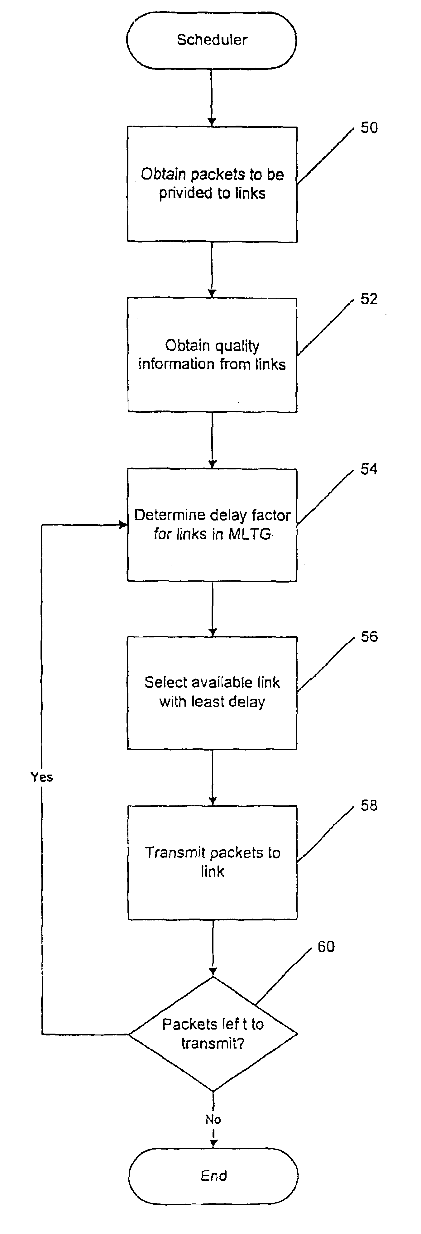
The present invention provides for scheduling of information packets to concurrent paths between two nodes in a communication path. The present invention is a form of “stripin...


PUM


Abstract

Methods, apparatus and computer program products are provided for distributing communication packets over multiple concurrent parallel links between a first node and a second node in a communication network based upon link quality information for the links. By utilizing link quality information from the links, the rate at which packets are provided to the links may be made proportional to the quality of the link, and thus, the link's ability to transmit the packet. The rate at which packets are provided to links may be reduced when error rates on a link exceed a specified threshold and eliminated when error rates exceed a higher threshold. Alternatively, timing delays from errors on a link may be used to determine a delay factor for a link and packets scheduled to the links based on the link with the lowest delay. The present invention is particularly useful in High Performance Routing Multilink Transmission Groups.

Description

FIELD OF THE INVENTIONThe present invention relates to communications networks and more particularly to communications networks having multiple physical links, paths, connections or virtual circuits between two nodes.BACKGROUND OF THE INVENTIONIn recent years there has been a proliferation in the networking of computer systems. The recent expansion of the Internet is just one example of the trend toward distributed computing and information sharing. In most forms of computer or communication networking there are communication paths between the computers in the networks. These paths may include multiple links or hops between intermediate equipment in a path. Thus, a communication may be originated by a first computer and pass through several links before reaching the destination computer. The control over these communications is typically carried out under a networking architecture. Many networking architectures exist for defining communications between computers in a network. For ex...

Claims


Application Information

Patent Timeline
Patent Type & Authority Patents(United States)
IPC IPC(8): H04L12/56
CPCH04L45/00H04L47/125H04L47/10H04L45/24
Inventor GRAY, JAMES P.MARTIN, JAMES J.
Owner IBM CORP
Why Eureka
Try Eureka