Rotary throttle valve carburetor

a technology of rotary throttle valve and carburetor, which is applied in the field of carburetors, can solve the problems of difficult control, excessive fuel supply at idle, and low speed engine operation, and achieve the effects of sufficient fuel flow rate, and convenient control of flow ra

Inactive Publication Date: 2006-10-03
NIPPON WALBRO KK
View PDF14 Cites 13 Cited by
  • Summary
  • Abstract
  • Description
  • Claims
  • Application Information

AI Technical Summary

Benefits of technology

[0005]According to another aspect of the invention, a fuel nozzle for a carburetor includes a body having a base adapted to be carried by the carburetor and an open end opposite the base, a central passage open to the open end, a groove open to the central passage and the open end, and a fuel orifice formed through a portion of the body and communicating the central passage with the exterior of the body. Fuel is provided through both the groove and the fuel orifice to facilitate control of the flow rate of fuel delivered from the carburetor over a wide range of engine operating conditions.
[0006]Some objects, features, advantages and aspects that may be achieved by at least some embodiments of the present invention include providing a carburetor that facilitates control of the flow rate at which fuel is delivered from the carburetor during operation at low engine fuel demand, provides sufficient fuel flow rates under high engine fuel demand operation, provides a gradual change in the effective flow area of a fuel nozzle over a predetermined range of engine operation with a relatively low fuel demand, improves engine performance, reduces hydrocarbon emissions from the engine, is of relatively simple design and economical manufacture and assembly, is rugged, durable and has in service a long useful life.

Problems solved by technology

In such a carburetor, because the negative pressure in the fuel and air mixing passage is relatively high at idle and low speed positions of the throttle valve, fuel supply at idle and low speed engine operation tends to be excessive and difficult to control.

Method used


Image

  • Rotary throttle valve carburetor
  • Rotary throttle valve carburetor
  • Rotary throttle valve carburetor

Examples


Embodiment Construction

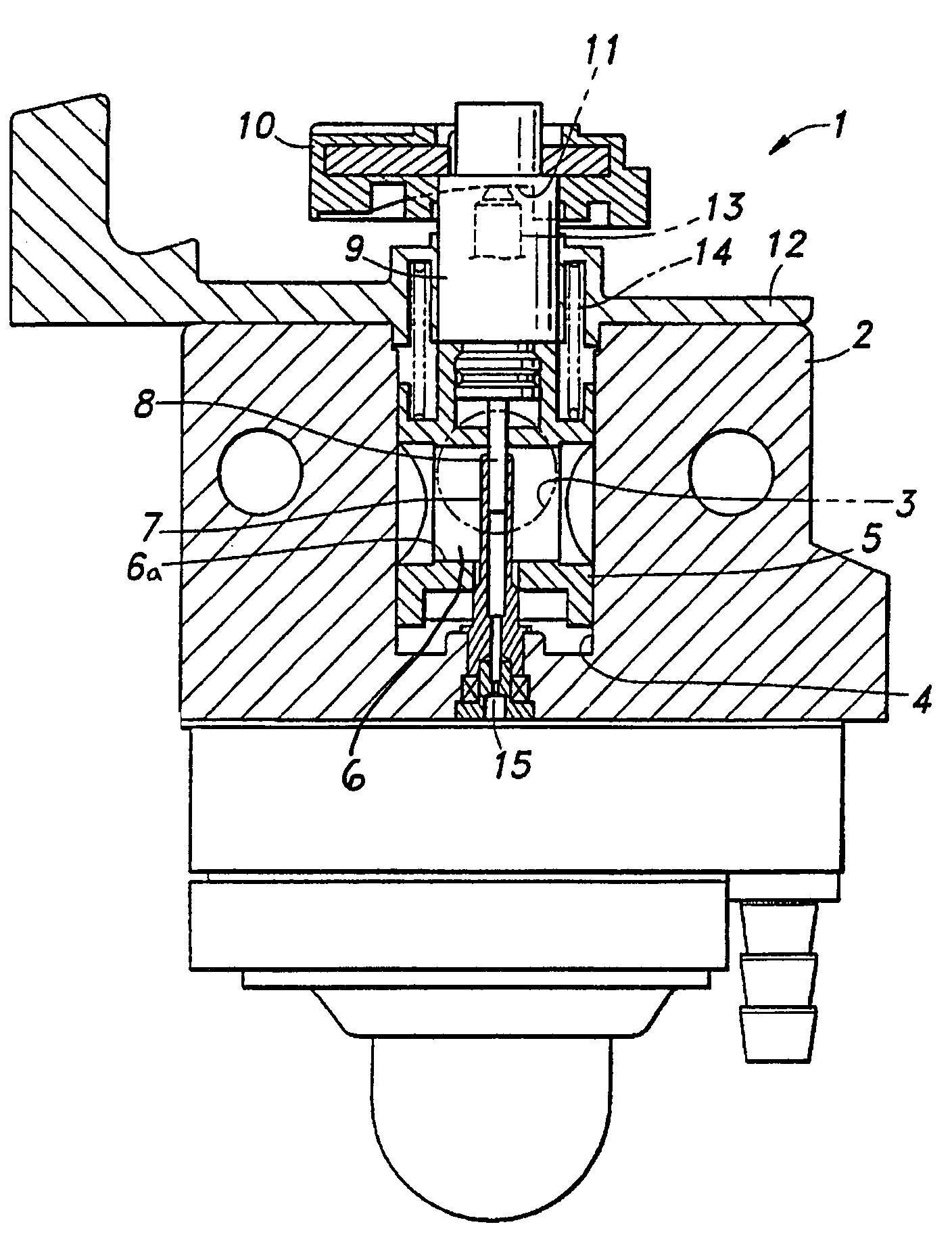
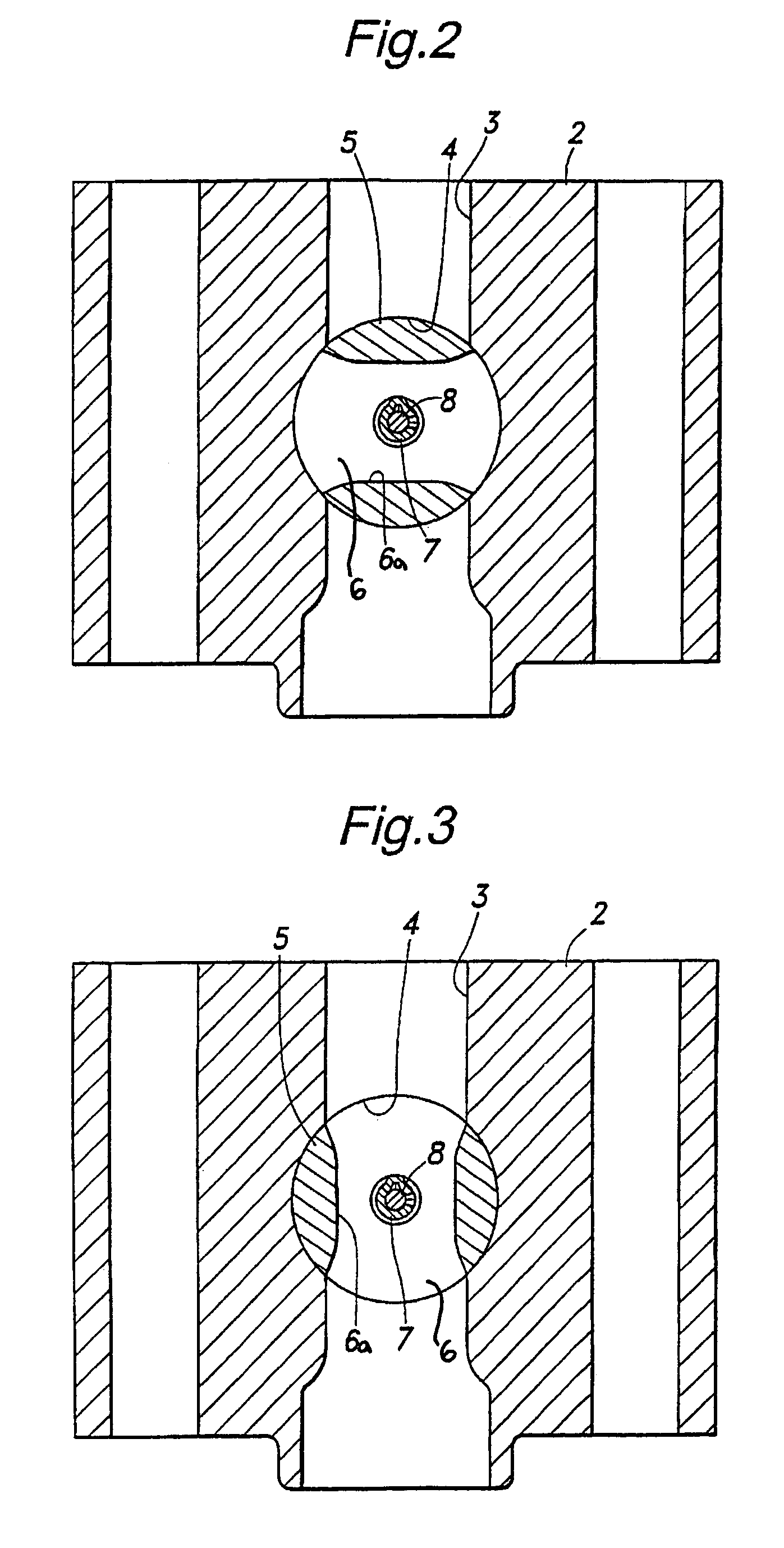
[0017]Referring in more detail to the drawings, FIG. 1 shows a rotary throttle valve carburetor according to one presently preferred embodiment of the invention. The carburetor 1 includes a carburetor main body 2, a fuel and air mixing passage 3 extending through the main body 2, a cylindrical valve chamber 4 formed in the main body 2 perpendicular to the fuel and air mixing passage 3, and a cylindrical rotary throttle valve 5 rotatably and slidably received in the valve chamber 4. The rotary throttle valve 5 includes a valve bore 6 that may have a venturi or reduced diameter neck portion 6a. The throttle valve 5 at least substantially closes the fuel and air mixing passage 3 when the throttle valve is in its idle position, (see FIG. 2), and preferably fully opens the fuel and air mixing passage 3 when the throttle valve 5 is in its wide or fully open position (see FIG. 3). The carburetor 1 further has a tubular fuel nozzle 7 projecting into the valve chamber 4 and the valve bore 6 ...


PUM

PropertyMeasurementUnit
areaaaaaaaaaaa
widthaaaaaaaaaa
axial lengthaaaaaaaaaa

Abstract

A rotary throttle valve carburetor includes a body having a fuel and air mixing passage and a throttle valve movable between idle and wide open positions. A valve bore is increasingly aligned with the fuel and air mixing passage as the throttle valve is moved from idle toward its wide open position. A fuel metering needle is responsive to movement of the throttle valve so that the needle moves relative to the body in response to movement of the throttle valve. A fuel nozzle extends into the valve bore, is associated with the fuel metering needle, and has a fuel ejection passage with an effective flow area controlled by movement of the fuel metering needle relative to the fuel nozzle and includes a portion with a cross-sectional area that gradually increases in the direction of fuel metering needle movement corresponding to throttle valve movement toward its wide open position.

Description

REFERENCE TO RELATED APPLICATION[0001]Applicants claim priority of Japanese Application Ser. No. 2003-167408, filed on Jun. 12, 2003.FIELD OF THE INVENTION[0002]The present invention relates generally to carburetors and more particularly to a rotary throttle valve carburetor.BACKGROUND OF THE INVENTION[0003]A rotary throttle valve carburetor comprises a carburetor main body having a fuel and air mixing passage formed therein, a cylindrical valve chamber formed in the main body perpendicular to the fuel and air mixing passage and, a rotary throttle valve received in the valve chamber for rotary and axial movement. The throttle valve includes a shaft with a through hole or passage that is increasingly aligned with the fuel and air mixing passage as the throttle valve is moved toward its open position. In such a carburetor, because the negative pressure in the fuel and air mixing passage is relatively high at idle and low speed positions of the throttle valve, fuel supply at idle and l...

Claims


Application Information

Patent Timeline
Patent Type & Authority Patents(United States)
IPC IPC(8): F02M9/08F02M17/08
CPCF02M9/085Y10S261/39
Inventor DOUYAMA, YOSHIAKIOHGANE, SHINICHITAKANO, JUNTOBINAI, TERUHIKO
Owner NIPPON WALBRO KK
Why Eureka
Try Eureka