Hydraulic tool

a technology of hydraulic fluid and tool, applied in the field of hydraulic tools, can solve the problems of affecting affecting the operation of hydraulic fluid, and requiring relatively large and heavy tools, and achieve the effect of facilitating the flow control of hydraulic liquid

Active Publication Date: 2005-08-18
MINIBOOSTER HYDRAULICS
View PDF5 Cites 13 Cited by
  • Summary
  • Abstract
  • Description
  • Claims
  • Application Information

AI Technical Summary

Benefits of technology

[0021] Preferably, parallel to each intensifier path a stop valve is provided that can be controlled by a pressure within the other intensifier path, respectively. This facilitates the flow control of hydraulic liquid in one or the other working direction when generating the high pressure.

Problems solved by technology

Such a pressure source has a limited output pressure.
In order to be able to provide the desired performance despite of this, the tools must be relatively large and heavy; this complicates their handling.
However, this configuration requires also a certain size and stability because the valve must control the higher pressure.

Method used


Image

  • Hydraulic tool
  • Hydraulic tool
  • Hydraulic tool

Examples


Embodiment Construction

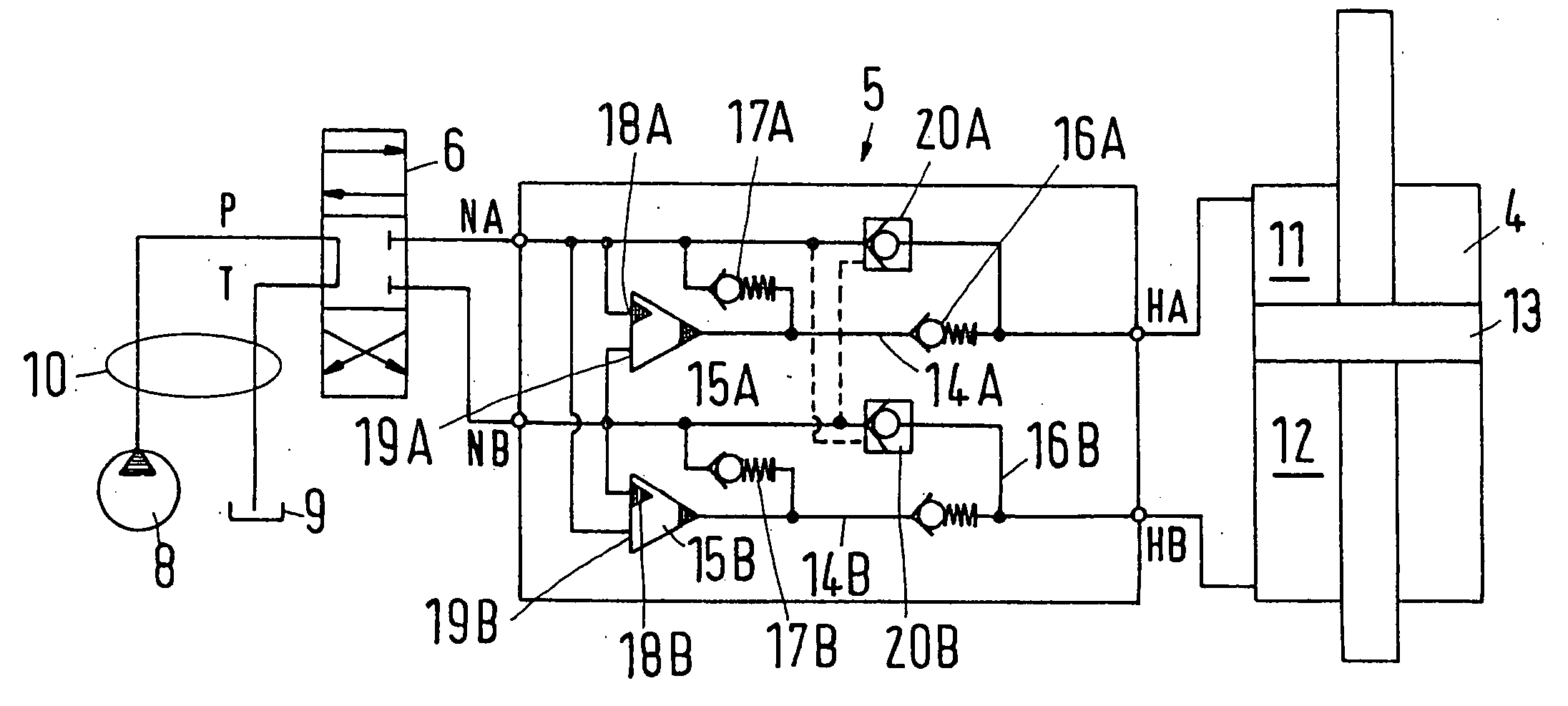
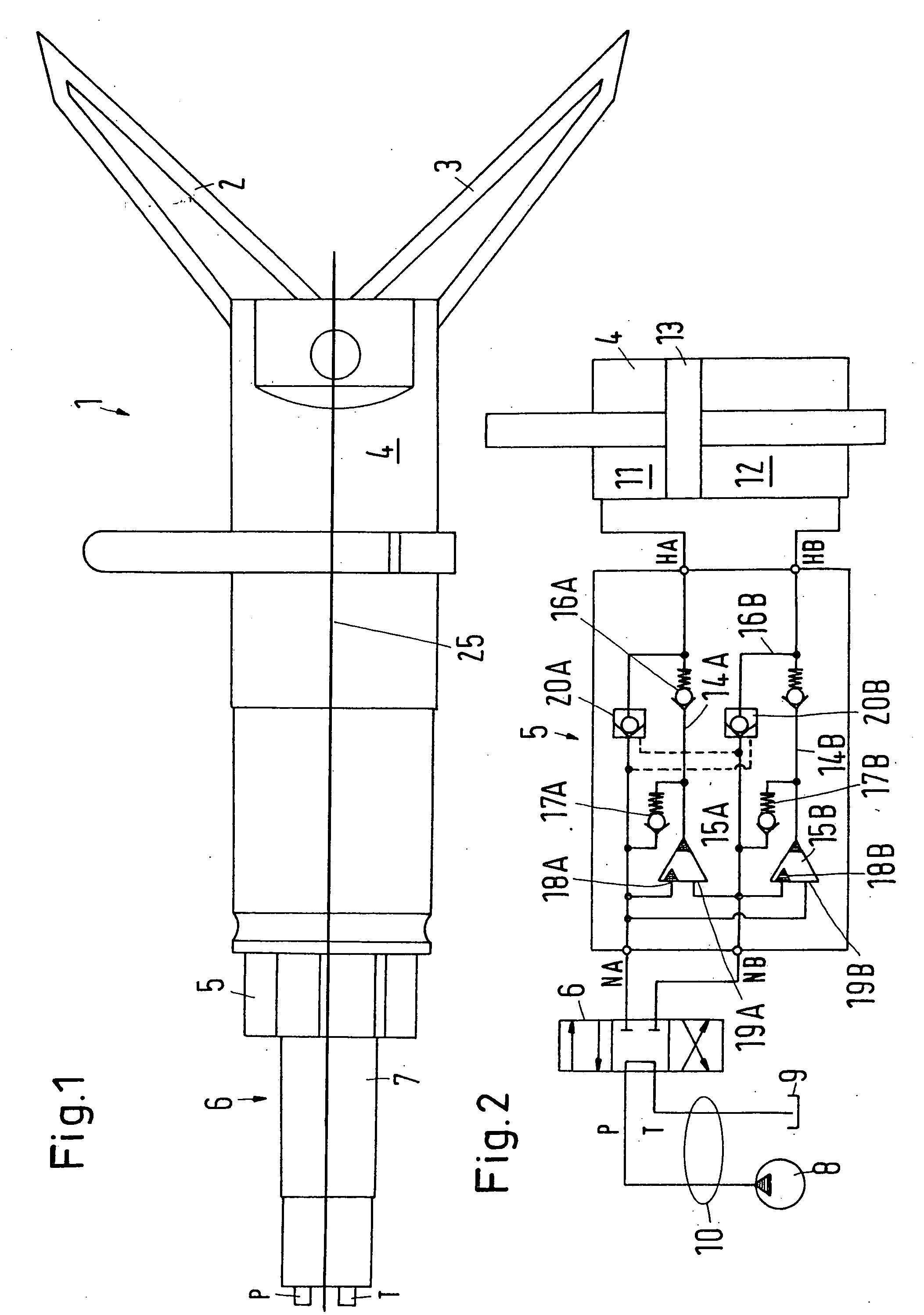
[0028] A portable hydraulic rescue tool 1 in the embodiment illustrated in FIG. 1 is in the form of shears. The shears have two jaws 2, 3 that are movable toward one another and are operated by a motor 4. As can be seen in FIG. 2, the motor 4 is a double-acting piston-cylinder device.

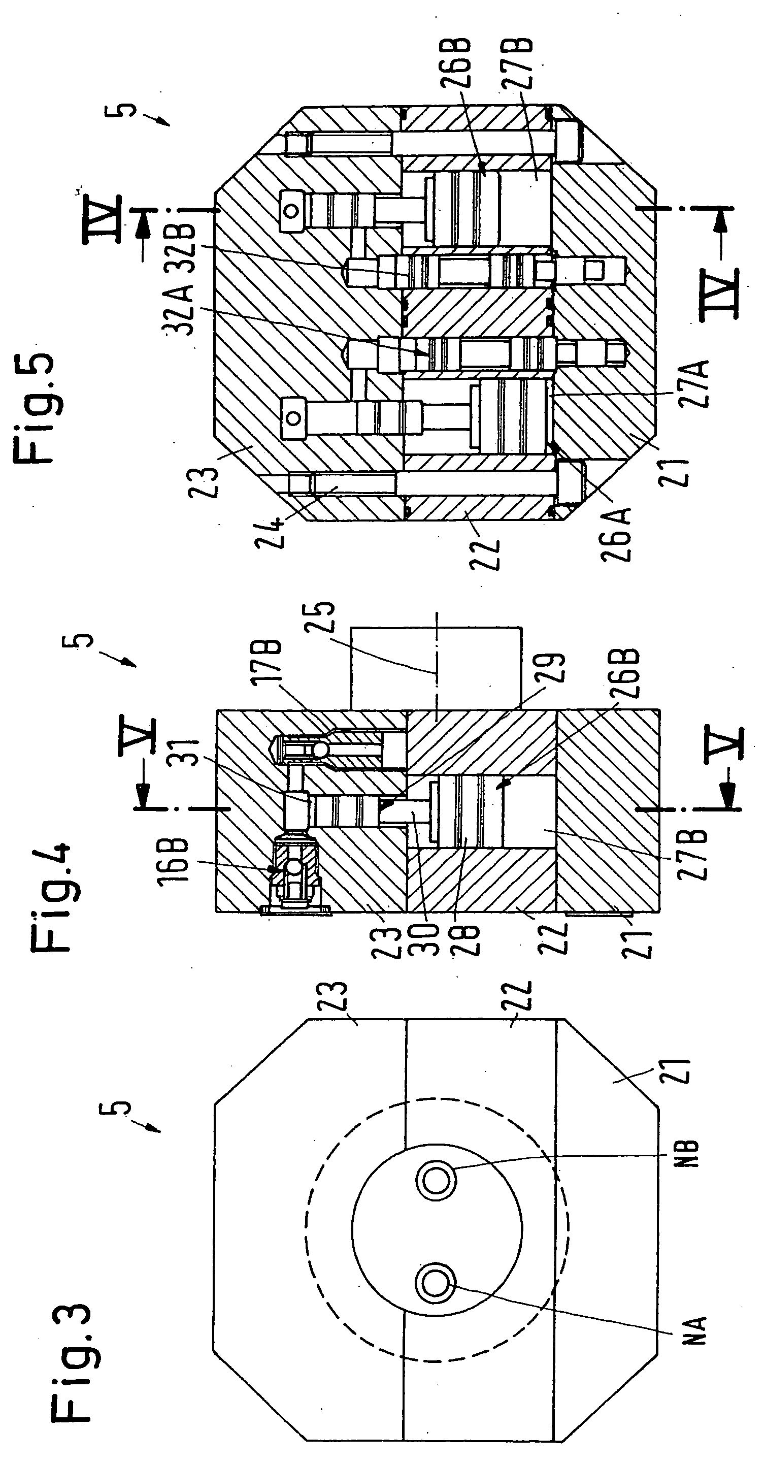
[0029] At the end of the motor 4 facing away from the jaws 2, 3, a hydraulic intensifier 5 is arranged that is attached to the motor 4 in a way not disclosed in detail. At the end of the hydraulic intensifier 5 facing away from the motor 4, a valve 6 is arranged that controls by means of a rotary grip 7 the direction of movement of the jaws 2, 3. The valve 6 in turn has a supply connector arrangement with a pump connector P and a tank connector T. The pump connector P, as shown in FIG. 2, is connected to a pump 8. The tank connector T is connected to a tank 9. Pump 8 and tank 9 can be arranged on a self-propelled device carrier, for example, a fire department vehicle. From there, the connection to the ...


PUM

PropertyMeasurementUnit
angleaaaaaaaaaa
angleaaaaaaaaaa
pressureaaaaaaaaaa

Abstract

A hydraulic tool has a motor, a valve, a hydraulic intensifier and a supply connector. The hydraulic intensifier is arranged between the valve and the motor. The valve and the motor are arranged behind one another in a longitudinal direction of the tool. The hydraulic intensifier has at least one intensifier piston having a movement direction that is positioned at a first angle greater than 0° relative to the longitudinal direction of the tool.

Description

BACKGROUND OF THE INVENTION [0001] 1. Field of the Invention [0002] The invention relates to a hydraulic tool comprising a motor, a valve, a hydraulic intensifier, and a supply connector. [0003] 2. Description of the Related Art [0004] The invention concerns in particular a transportable hydraulic rescue tool. Such a rescue tool can be configured as a hydraulic cutting device, a hydraulic spreader, a combination device, a cutter for pedals, a lifting device or a similar device. For example, a cutting device that is configured as hydraulic shears is required in order to be able to free in an automobile accident passengers of a greatly deformed motor vehicle. [0005] Conventionally, such tools are supplied by a pressure source that is transported on a vehicle. Such a pressure source has a limited output pressure. In order to be able to provide the desired performance despite of this, the tools must be relatively large and heavy; this complicates their handling. [0006] It has therefore ...

Claims


Application Information

Patent Timeline
Patent Type & Authority Applications(United States)
IPC IPC(8): A62B99/00B23D17/06B23D29/00B23D29/02B25F3/00B60T13/00F15B3/00
CPCB23D29/02B23D17/06
Inventor HANSEN, LEIFESPERSEN, CHRISTENBOLLMANN, THYGECLAUSEN, PETER J.M.
Owner MINIBOOSTER HYDRAULICS
Why Eureka
Try Eureka