Organic electroluminescence element

a technology of electroluminescence element and organic light, which is applied in the direction of luminescent composition, organic chemistry, thermoelectric devices, etc., can solve the problems that the need for high luminous efficiency and stable long-term operation is not fully met, and achieves the effect of long operation lifetime and high luminous efficiency

Active Publication Date: 2005-07-21
UDC IRELAND +1
View PDF7 Cites 52 Cited by
  • Summary
  • Abstract
  • Description
  • Claims
  • Application Information

AI Technical Summary

Benefits of technology

[0019] According to this aspect of the present invention, a high-performance organic EL display usin

Problems solved by technology

However, the need for materials that have high luminous efficiency and are stable in a long duration of operati

Method used


Image

  • Organic electroluminescence element
  • Organic electroluminescence element
  • Organic electroluminescence element

Examples


example 1

Synthesis of 1,3,6,8-tetra(4-phenoxyphenyl)pyrene Represented by the Formula Below

[0141]

[0142] 1,3,6,8-tetrabromopyrene was obtained by the reaction of one equivalent of pyrene and 4 times as much as bromine in equivalent in a nitrobenzene, according to the method described in Annalen der Chemie, vol. 531, p. 81.

[0143] Next, 4.4 equivalents of 4-phenoxyphenylboronic acid, 10 equivalents of sodium carbonate in a 2 mol / L aqueous solution, and 0.12 equivalents of tetrakis(triphenylphosphine)palladium (0) were added to one equivalent of 1,3,6,8-tetrabromopyrene, and the mixture was subjected to heating under refluxing to allow reaction for three hours, using benzene as a solvent.

[0144] After cooling the reaction product, the deposit formed by adding methanol to the reaction product was washed with water, and recrystallized from THF-methanol to obtain a crude product. The crude product was purified by sublimation in vacuo, to form a compound for the purpose.

[0145] An o-xylene solutio...

example 2

Synthesis of 1,3,6,8-tetrakis[3-(3-methyldiphenylamino)phenyl]pyrene Shown in the Following formula

[0146]

[0147] 4.4 equivalents of 3-chlorophenylboronic acid, 10 equivalents of sodium carbonate in a 2 mol / L aqueous solution, and 0.12 equivalents of tetrakis(triphenylphosphine)palladium (0) were added to one equivalent of 1,3,6,8-tetrabromopyrene obtained in the same way as for EXAMPLE 1, and the mixture was subjected to heating under refluxing to allow reaction for three hours, using benzene as a solvent. 1,3,6,8-tetra(3-chlorophenyl)pyrene was obtained after deposition and purification through recrystallization of the product.

[0148] 4.4 equivalents of 3-methyldiphenylamine, 10 equivalents of sodium tert-butoxide, 0.01 equivalent of palladium acetate, and 0.04 equivalents of tri-tert-butyl phosphine were added to this 1,3,6,8-tetra(3-chlorophenyl)pyrene in an amount of one equivalent, and the mixture was subjected to heating under refluxing to allow reaction for three hours, using...

example 3

Synthesis of 1,3,6,8-tetrakis[3,5-bis(3-methyldiphenylamino)phenyl]pyrene Shown in the Following Formula

[0151]

[0152] According to the same processes as for EXAMPLE 2, except that 3,5-dichlorophenylboronic acid was used instead of 3-chlorophenylboronic acid, and 8.8 equivalents of 3-methyldiphenylamine was used instead of 4.4 equivalents, 1,3,6,8-tetrakis[3-(3-methyldiphenylamino)phenyl]pyrene was obtained.

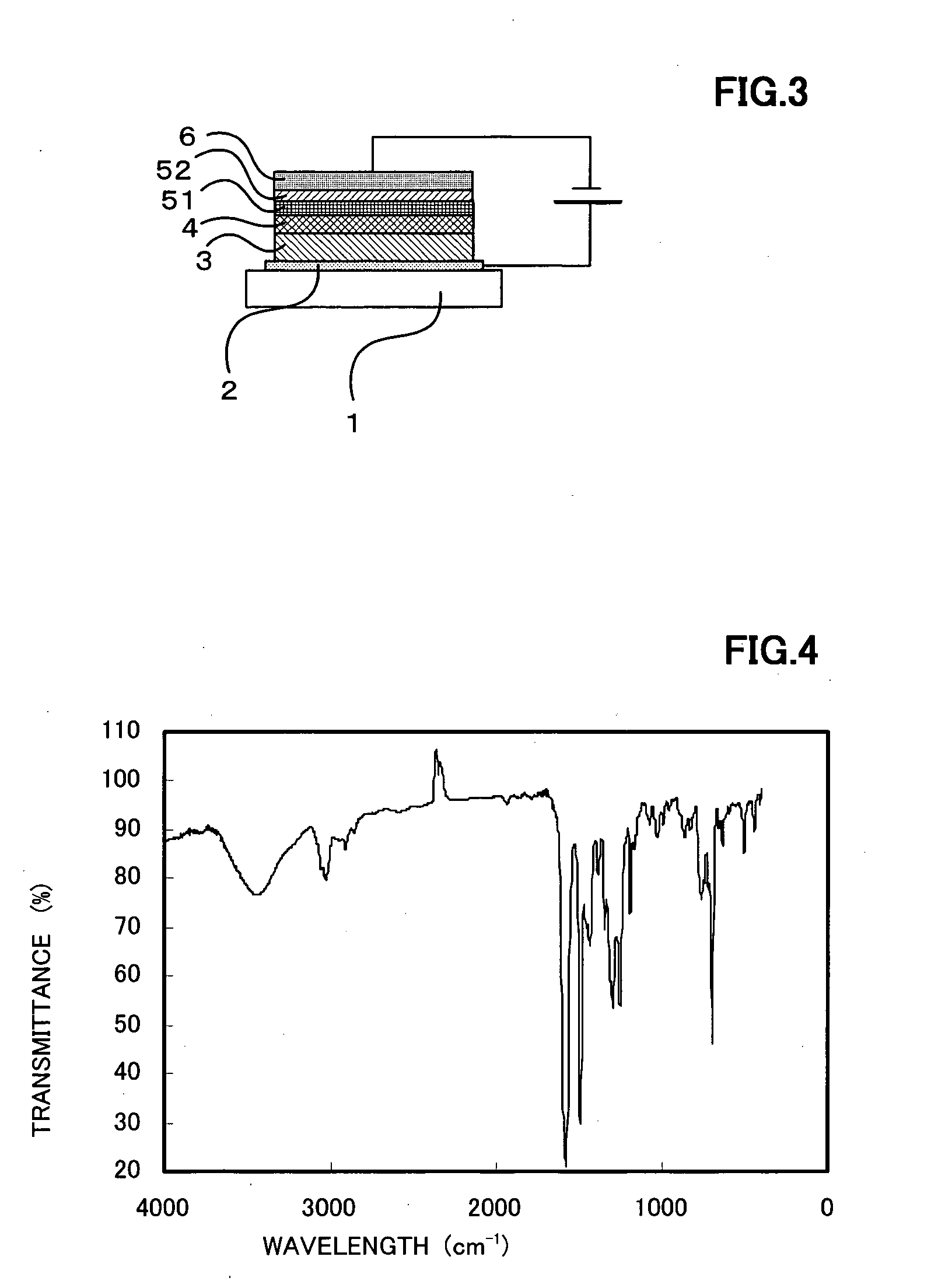
[0153] An o-xylene solution of the compound showed a strong blue fluorescence, by irradiating with ultraviolet rays having a wavelength of 365 nm. The molecular weight of the compound by the mass spectrum was 1,954, coinciding with the expected value for the molecular formula (C144H114N8). The IR spectrum of the compound in KBr is shown in FIG. 4.


PUM


Abstract

This organic electroluminescence element has an organic light-emitting layer between a positive electrode and a negative electrode, wherein the organic light-emitting layer contains a 1,3,6,8-tetrasubstituted pyrene compound having a specific structure as an organic light-emitting layer forming material. Provided are an organic light-emitting layer forming material that emits blue light with a high color purity, has a high luminous efficiency, and is stable for a long duration of operation, when used singly or as a guest, an organic EL element having a high luminous efficiency and a long operation lifetime, and a high-performance organic EL display that has a high luminous efficiency and a long operation lifetime.

Description

CROSS REFERENCE TO RELATED APPLICATIONS [0001] This application is a continuation of international application PCT / JP2003 / 005417, filed on Apr. 28, 2003.BACKGROUND OF THE INVENTION [0002] 1. Field of the Invention [0003] The present invention relates to an organic light-emitting layer forming materials for an organic electroluminescence element (also called an organic EL element, hereinafter), an organic EL element, and organic EL display. [0004] 2. Description of the Related Art [0005] Since a layer-type element in which a positive hole transporting organic thin film and electron transporting organic thin film were layered, was reported (C. W. Tang and S. A. VanSlyke, Applied Physics Letters, vol. 51, p. 913, 1987, for example), organic EL elements have been expected to be applied to flat panel displays as display elements having features such as self emission and high-speed response. They are a focus of particular interest as large-area light-emitting elements that emit light at a...

Claims


Application Information

Patent Timeline
IPC IPC(8): C07C211/54C09K11/06H01L35/24H01L51/00H01L51/50H05B33/14
CPCC07C211/54C09K11/06C09K2211/1011H01L51/0054H05B33/14H01L51/0062H01L51/0079H01L51/0081H01L51/5012H01L51/006C07C43/275C07C2603/50H10K85/649H10K85/622H10K85/633H10K85/321H10K85/324H10K50/11
Inventor SOTOYAMA, WATARU
Owner UDC IRELAND
Why Eureka
Try Eureka