High-pressure discharge lamp and arc tube with long operating lifetime and high impact resistance

a high-pressure discharge lamp and arc tube technology, which is applied in the direction of electric discharge tubes, gas discharge lamps details, electrical apparatus, etc., can solve the problems of micro cracks in frit glass, inability to ensure a sufficient lamp life, and corrosion at a brush

Inactive Publication Date: 2003-11-18
PANASONIC CORP
View PDF3 Cites 7 Cited by
  • Summary
  • Abstract
  • Description
  • Claims
  • Application Information

AI Technical Summary

Benefits of technology

With the stated construction, a portion of the first conductive member of at least one of the feeders that is located inside the capillary tube part is halogen-resistant, which reduces the possibility of the feeder being corroded by halides that have penetrated in the seal member during the lighting. This prevents an enclosed substance from being leaked to outside. Also, the feeder has a second conductive member located outside the capillary tube part, which is different from the first conductive member. With the use of a material that has a great mechanical strength or is flexible, and with the second conductive member being fixed with a fixing member, it is possible to prevent a breakage of the feeder on external impact or vibration, thereby extending the lamp life.
To achieve the second object of the present invention, the arc tube related to the present invention has an arc tube including an arc vessel including a main tube part and a pair of capillary tube parts, the main tube part having an inner discharge space, the capillary tube parts continuing into the discharge space; a pair of electrodes being opposed to each other in the discharge space: a pair of feeders, each of which is inserted through a different one of the capillary tube parts with an end connected to one of the electrodes on a side of the feeder and a remaining end protruding from the capillary tube part to outside; and a seal member for sealing the feeders in the capillary tube parts, wherein at least one of the feeders includes a first conductive member being sealed in the capillary tube part and a second conductive member being connected to the first conductive member outside the capillary tube part, the first conductive member being resistant to halides, the second conductive member being fixed with a fixing member at an end of the capillary tube part. With the stated construction, a portion of the first conductive member of at least one of the feeders that is located inside the capillary tube part is halogen-resistant, which reduces the possibility of the feeder being corroded by halides that have penetrated in the seal member during the lighting. This prevents an enclosed substance from being leaked to outside. Also, the feeder includes a second conductive member located outside the capillary tube, which is different from the first conductive member. With the use of a material that has a greater mechanical strength or flexibility, and by fixing the second conductive member to the capillary tube part by means of a suitable fixing member, the breakage of the feeder on external impact or impact can be prevented, and thus an arc tube having a longer operating lifetime can be obtained.

Problems solved by technology

However, it was found in the actual fact that a leak of halides can occur in the sealed area even with the stated construction, which makes it impossible to ensure a sufficient lamp life.
As a result, every time the light is turned on and off, micro cracks are formed in the frit glass, in an area extending from the end of the seal member on the side of the discharge space to the other end of the feeder.
However, since niobium is easily corroded by halides, corrosion can advance at a brush, once the halides that are penetrating into those micro cracks reach the surface of the niobium.
This results in the occurrence of a space in places where niobium contacts with the seal member, causing a leak of metal halides enclosed inside the seal member, thereby rapidly decreasing luminous efficacy of the lamp.
However, this material is of low mechanical strength, and a portion of the conductive cermet that is protruding from a capillary tube part is easily broken by external impact and vibration.
Therefore, if the protruding part is broken by external impact, the metal halide lamp becomes unusable.
Therefore, the above problem can occur in these high-pressure discharge lamps, too.
With the stated construction, a portion of the first conductive member of at least one of the feeders that is located inside the capillary tube part is halogen-resistant, which reduces the possibility of the feeder being corroded by halides that have penetrated in the seal member during the lighting.
This further reduces the possibility of the feeder being broken off.
With the stated construction, the fringe is strong enough to be used for a backup use, which further reduces the possibility of the feeder being broken off.
This further reduces the possibility of the feeder being broken off.
This further reduces the possibility of the second conductive member being broken off.
With the stated construction, a portion of the first conductive member of at least one of the feeders that is located inside the capillary tube part is halogen-resistant, which reduces the possibility of the feeder being corroded by halides that have penetrated in the seal member during the lighting.

Method used


Image

  • High-pressure discharge lamp and arc tube with long operating lifetime and high impact resistance
  • High-pressure discharge lamp and arc tube with long operating lifetime and high impact resistance
  • High-pressure discharge lamp and arc tube with long operating lifetime and high impact resistance

Examples


first embodiment

(First Embodiment)

The Constructions of an Arc Tube and a Metal Halide Lamp

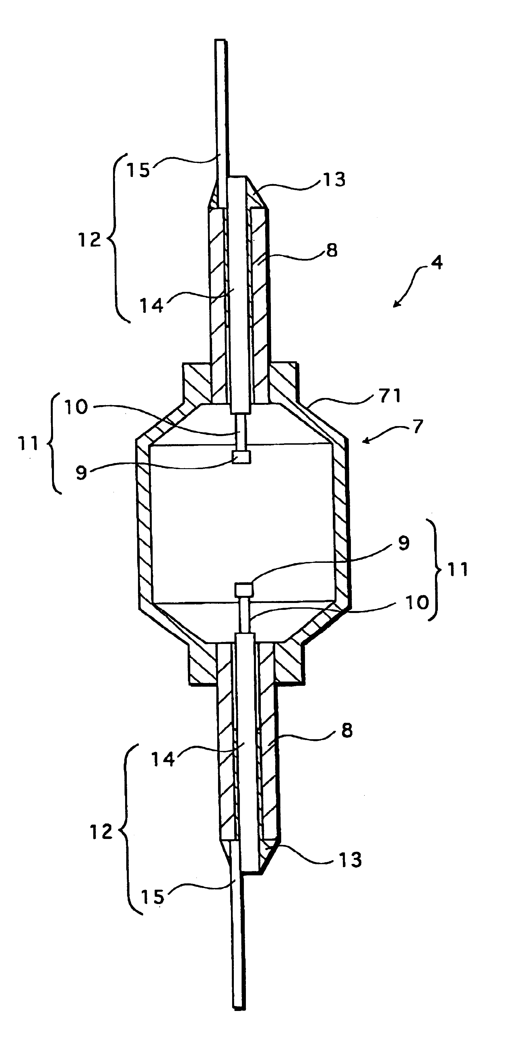
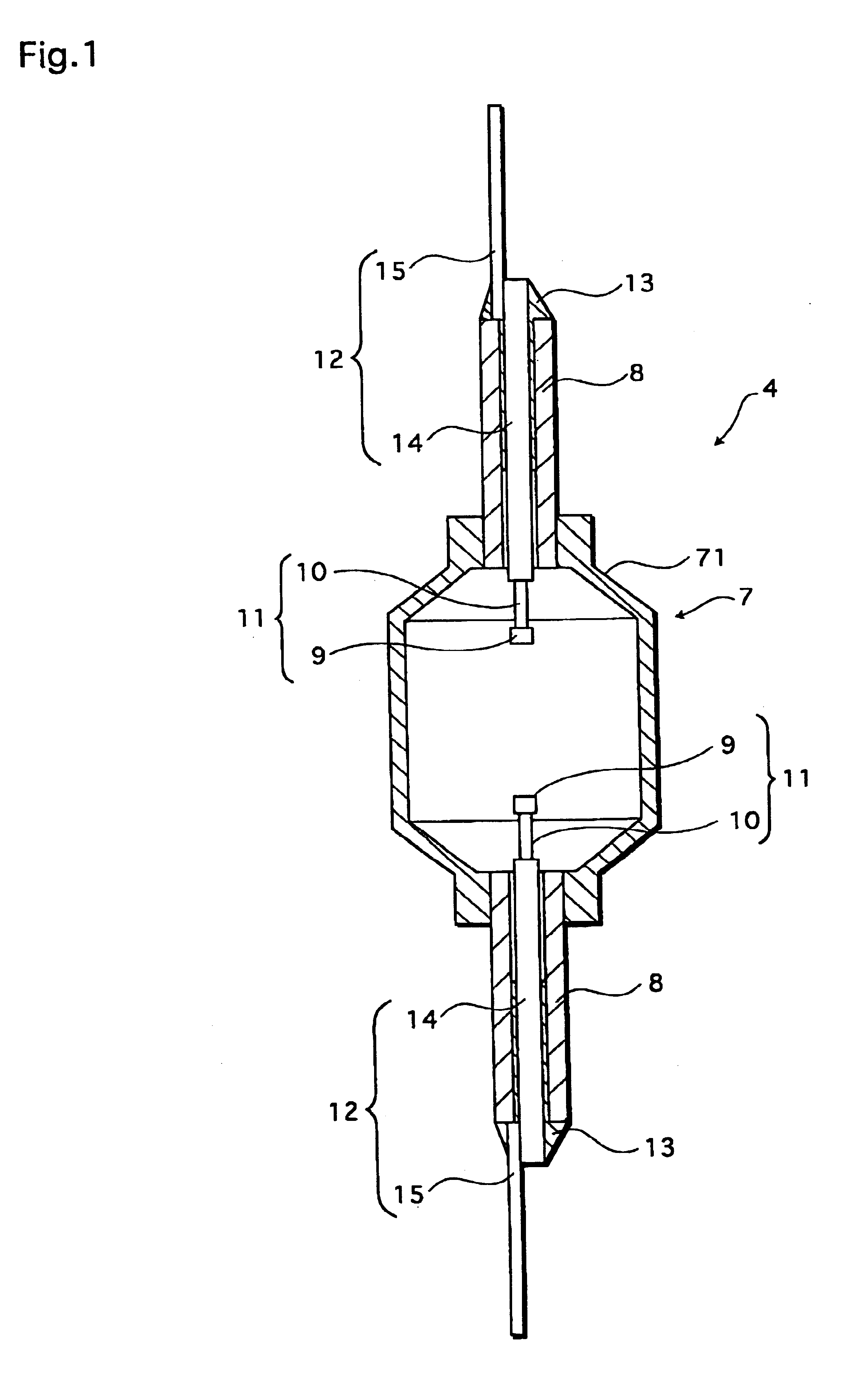
FIG. 1 is a sectional view showing the construction of an arc tube 4 of a metal halide lamp of the first embodiment.

A vessel containing the arc tube 4, which is an arc vessel, is a ceramic vessel that is made of alumina (whose thermal expansion coefficient is 8.1.times.10.sup.-6), and has a main tube part 71 with an inner volume of 1.1 cm.sup.3, and a pair of cylindrical capillary tube parts 8 arranged at the ends of the main tube part 71.

The emission part 7 of the arc tube 4 includes, inside an internal discharge space of the main tube part 71, a predetermined metal halide and a pair of opposing electrodes 11. In the capillary tube part 8, a first conductive member 14 of a feeder 12 is sealed with a seal member 13.

The feeder 12 has the first conductive member 14 and the second conductive member 15, which are arranged side by side, and the end of the first conductive member 14 and the second conductive member ...

second embodiment

(Second Embodiment)

A metal halide lamp of the second embodiment has the same structure except for a-feeder in the arc tube 4.

FIG. 5 is an enlarged cross-sectional view of a capillary tube part 8 of the arc tube 4 in the second embodiment.

Note that construction elements which are the same as those shown in FIG. 1 are given the same reference numerals, and their explanation is omitted here for the sake of convenience. The rest of the embodiments are described in the same manner.

Referring to FIG. 5, a second conductive member 17 of a feeder 16 is a niobium cylinder that is 20 mm long and has an inner diameter of 0.94 mm. One end of a first conductive member 14 that is protruding from the capillary tube part 8 by about 3 mm is arranged inside a second conductive member 17 and electrically connected to the second conductive member 17 by laser welding, or the like.

In the sealing processing described above, the connecting portion where the first conductive member 14 is connected to the sec...

third embodiment

(Third Embodiment)

FIG. 8 is a cross-section showing the construction of one of the capillary tube parts 8 in the arc tube 4 in a metal halide lamp, which is the third embodiment.

Referring to FIG. 8, a feeder 18 includes a first conductive member 14, with one end inserted into a cylindrical second conductive member 19. The third embodiment differs from the second embodiment in that a fringe 20 is formed at the bottom of the second conductive member 19.

FIG. 9 is a perspective view, with portions broken away, of the second conductive member 19.

Referring to FIG. 9, the fringe 20 is formed at the bottom of the cylindrical second conductive member 19. It is preferable that a diameter of the fringe 20 is smaller than 4.0 mm, which is an outer diameter of the capillary tube part 8, so that a liquid seal member 13, having melted during the sealing processing, is introduced into the upper side of the fringe 20. The example fringe 20 shown here has an outer diameter of 2.5 mm and a thickness o...


PUM


Abstract

A high-pressure discharge lamp having an arc tube that includes a main tube part and a pair of capillary tube parts is provided. The main tube part includes a pair of electrodes and a metal halide enclosed, and the pair of capillary tube parts is arranged at the of the main tube part. The pair of capillary tube parts is sealed by means of a seal member to a different one of the feeders, and supplies electricity to each of the electrodes. At least one of the feeders includes a first conductive member that is resistant to halides and sealed to the capillary tube part, and a second conductive member that is connected to the first conductive member outside the capillary tube part and fixed at an outer end of the capillary tube part by means of the seal member.

Description

(1) Field of the InventionThe present invention relates to a high-pressure discharge lamp and an arc tube built in the high-pressure discharge lamp.(2) Related ArtAs an example of conventional high-pressure discharge lamps, there is a known metal halide lamp that is disclosed in the Japanese Laid-Open Patent Application No. H06-196131.This metal halide lamp includes an arc tube having a main tube part and a pair of capillary tube parts. The main tube part has a pair of electrodes arranged opposite to each other in an internal discharge space. The pair of capillary tube parts is disposed at both ends of the main tube part and continues into the discharge space. In each of the capillary tube parts, there arranged a rod-like feeder for providing a current the corresponding electrode carries from outside. The feeder is sealed to the capillary tube part with a seal member such as frit glass.The feeder consists of two different types of metal which are connected into a rod. That is to say...

Claims


Application Information

Patent Timeline
Patent Type & Authority Patents(United States)
IPC IPC(8): H01J61/36
CPCH01J61/366H01J61/36H01J61/363
Inventor HIGASHI, MASANORINISHIURA, YOSHIHARUMANIWA, TAKASHI
Owner PANASONIC CORP
Why Eureka
Try Eureka