Hydrodynamic bearing device, and spindle motor and information device using the same

a technology of hydrodynamic bearings and information devices, which is applied in the direction of bearings, shafts and bearings, instruments, etc., can solve the problems of high manufacturing cost, low viscosity of air, and precise machining, and achieve high reliability, high performance, and long operation life.

Active Publication Date: 2009-02-24
PHC HLDG CORP
View PDF15 Cites 8 Cited by
  • Summary
  • Abstract
  • Description
  • Claims
  • Application Information

AI Technical Summary

Benefits of technology

[0013]The present invention has the objective of providing a hydrodynamic bearing device, spindle motor and information device with a long operational lifetime that is suitable for miniaturization, that has high reliability and high performance through superior heat resistance (specifically, even in a high temperature environment) and by utilizing a dynamic pressure-generating liquid with little loss due to evaporation.
[0014]Also, the present invention has the objective of providing a hydrodynamic bearing device that reduces the amount of the dynamic pressure-generating liquid to be filled in each device due to a reduction in the amount of evaporation of the dynamic pressure-generating liquid, as well as eliminates the need for the location and space for filling an excess of the dynamic pressure-generating liquid, so that the cost can be lowered and the device is suitable for miniaturization.

Problems solved by technology

However, the viscosity of air is low and requires extremely thin gaps and broad facing surfaces in order to generate pressure in the gap, and to achieve this requires highly precise machining.
The cost of manufacturing increases as a result.
However, while these conventional dynamic pressure-generating liquids of the hydrocarbon series have low viscosity and can reduce torque, their heat resistance is lower (higher vapor pressure) due to the characteristics of their molecular structure, and the amount of evaporation produced will increase as they reach a high temperature.
For this reason, if used continuously in a high temperature environment, the amount of dynamic pressure-generating liquid required for the rotation of the bearing cannot be maintained.
For the amount of evaporation of the dynamic pressure-generating liquid considered previously, the above requirement makes it necessary to fill with an excess of the dynamic pressure-generating liquid, but the space and location required in order to fill with an excess of the dynamic pressure-generating liquid result in the miniaturization of the hydrodynamic bearing device and reductions in the cost becoming difficult.

Method used


Image

  • Hydrodynamic bearing device, and spindle motor and information device using the same
  • Hydrodynamic bearing device, and spindle motor and information device using the same
  • Hydrodynamic bearing device, and spindle motor and information device using the same

Examples


embodiment 1

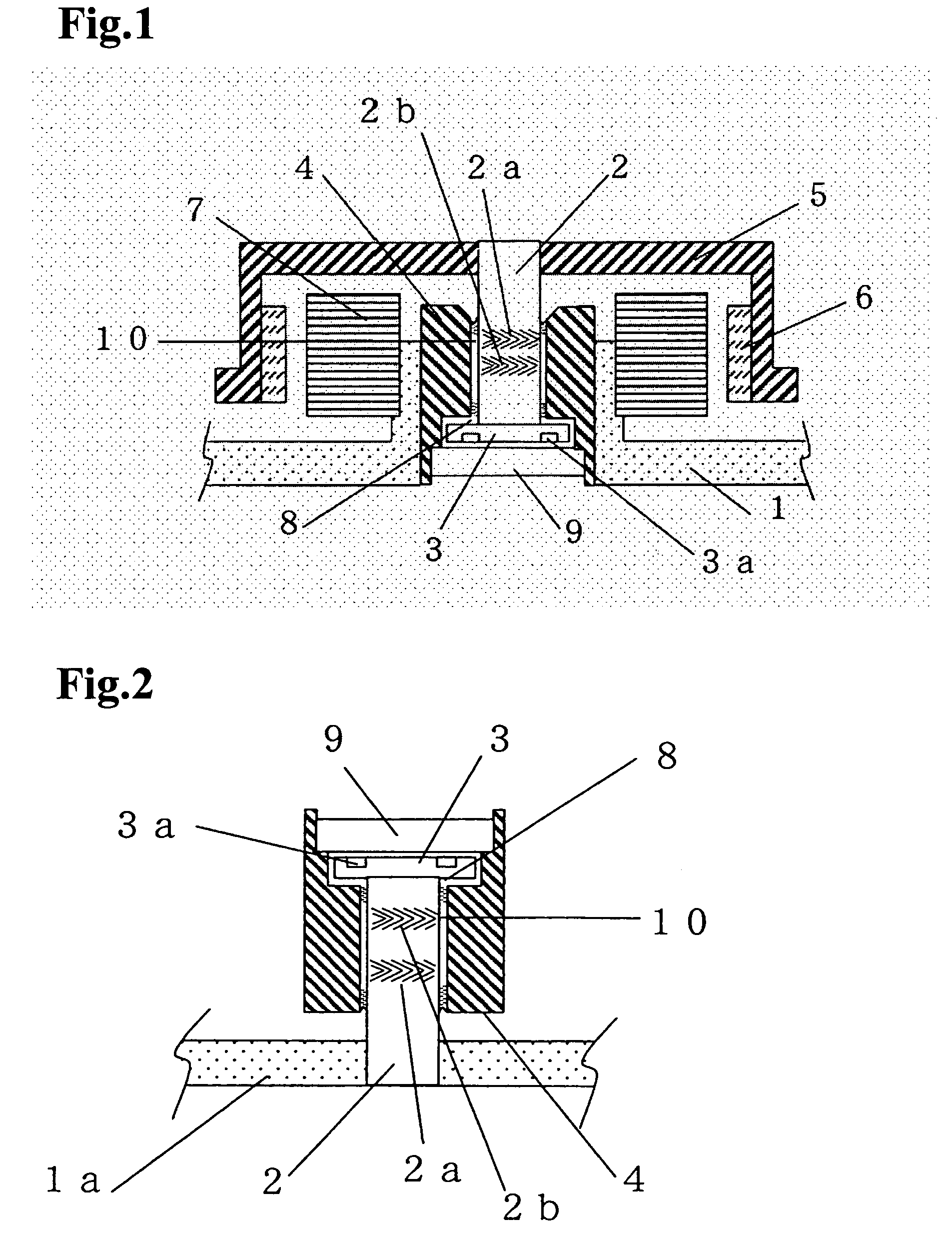
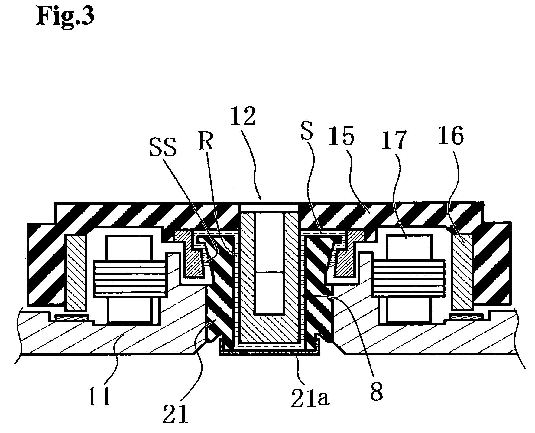
[0020]Embodiment 1 of the present invention is described with reference to FIG. 2. FIG. 2 is a cross section drawing of the main component for a hydrodynamic bearing device in a fixed shaft type of Embodiment 1.

[0021]In FIG. 2, radial dynamic pressure-generating grooves 2a and 2b are formed in a herringbone pattern on the outer circumferential surface of shaft 2. One end of the shaft 2 is affixed to thrust flange 3, and the other end is press fitted into base 1a. Shaft 2 and thrust flange 3 form the shaft component. The shaft component and the base 1a constitute the fixed component.

[0022]On the one hand, sleeve 4 possesses a bearing bore that supports the shaft component. Thrust plate 9 is mounted on one end of sleeve 4. The shaft component is inserted into the bearing bore of sleeve 4 in such a manner as to face thrust plate 9 and thrust flange 3. Sleeve 4 and thrust plate 9 constitute the rotator. Thrust dynamic pressure-generating groove 3a is formed in a spiral pattern on the su...

embodiment 2

[0030]Embodiment 2 of the present invention is explained by using FIG. 1. FIG. 1 is a cross section drawing of the main component of a magnetic disk device equipped with a spindle motor that possesses a rotating shaft-type hydrodynamic bearing device of Embodiment 2. The hydrodynamic bearing device in this Embodiment differs from the hydrodynamic bearing device in Embodiment 1 in FIG. 2 in the point that the present Embodiment has a rotating shaft type while Embodiment 1 has a fixed shaft type, and has the thrust dynamic pressure-generating grooves such as a herringbone pattern. With the exception of this point, Embodiment 2 is identical to Embodiment 1, and any of the elements having identical symbols have been omitted from the explanation.

[0031]In FIG. 1, radial dynamic pressure-generating grooves 2a and 2b are formed in a herringbone pattern on the outer circumferential surface of shaft 2, and the one end of shaft is affixed to thrust flange 3, and the other end is press fitted i...

embodiment 3

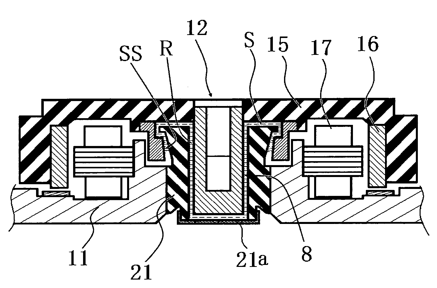
[0037]FIG. 3 is a cross section drawing of the main component of a magnetic disk device equipped with a spindle motor that possesses a rotating shaft-type hydrodynamic bearing device.

[0038]In this magnetic disk device, a sleeve 21, pressure fitted into the center of base 11, possesses a bearing bore that bears the shaft 12. Stator coil 17 is mounted on a wall formed by the base 11. The shaft 12 is inserted into the bearing bore of sleeve 21 from one end and the other end of the bearing bore is closed over by a cap 21a. Radial dynamic pressure-generating grooves (not shown) are formed in a herringbone pattern on the outer circumferential surface of shaft 12. The one end of shaft 12 is press fitted into hub 15 and the other end of shaft 12 is opposed to the cap 21a. The outer circumferential surface of the shaft 12 (a dynamic-pressure surface) radially opposes the inner circumferential surface of the sleeve 21 (a dynamic-pressure surface). They have a gap R interposed therebetween, an...


PUM

PropertyMeasurementUnit
viscosity indexaaaaaaaaaa
surface tensionaaaaaaaaaa
sizeaaaaaaaaaa

Abstract

A hydrodynamic bearing device has high reliability and is suitable for miniaturization through superior heat resistance and by utilizing a dynamic pressure-generating liquid with little loss due to evaporation. The hydrodynamic bearing device has at least one of a shaft structure and a sleeve having a dynamic pressure-generating mechanism. The dynamic pressure-generating liquid present in a gap between the shaft structure and the sleeve has a main component that is ionic liquid.

Description

BACKGROUND OF THE INVENTION[0001]1. Field of the Invention[0002]The present invention relates to a dynamic pressure-type hydrodynamic bearing device, as well as a spindle motor and information device using the same.[0003]2. Description of the Prior Art[0004]A hydrodynamic bearing device comprises a shaft and a sleeve that supports the shaft, and a dynamic pressure-generating liquid that is interposed in the gap between the two parts. With rotation of the shaft, the dynamic pressure-generating liquid is gathered up by dynamic pressure-generating grooves that are formed on the shaft or sleeve, and generates pressure such that the shaft is supported within the sleeve without coming into contact therewith. As a result, high-speed rotation can be attained, and ambient noise during the rotation can be alleviated.[0005]A spindle motor equipped with such a hydrodynamic bearing device can provide the requisite rotational accuracy with an increased recording density of the medium, and can fur...

Claims


Application Information

Patent Timeline
Patent Type & Authority Patents(United States)
IPC IPC(8): G11B17/02F16C32/06F16C33/10
CPCG11B19/2018G11B25/043F16C17/107
Inventor OHNO, HIDEAKIHIRATA, KATSUSHISHIRAISHI, TAKANORI
Owner PHC HLDG CORP
Why Eureka
Try Eureka