Hybrid polymer light-emitting devices

a light-emitting device and hybrid technology, applied in solid-state devices, layered products, electrical devices, etc., can solve the problems of short response time, low work function cathode and/or thin interfacial layer, and inability to meet the requirements of polymer layers, etc., to achieve short response time, excellent current-rectification diode properties, and long operating life

Inactive Publication Date: 2010-06-29
RGT UNIV OF CALIFORNIA
View PDF10 Cites 7 Cited by
  • Summary
  • Abstract
  • Description
  • Claims
  • Application Information

AI Technical Summary

Benefits of technology

[0017]An advantage of the mixtures and light-emitting devices of the present invention are that they exhibit excellent current-rectification diode properties, short response time, a single-phase active layer, and long operating lifetime. Neither the use of a low work function metal nor an interfacial layer is required to achieve good electron injection from the cathode. The ions inside the luminescent semiconducting polymer can be redistributed by applying a voltage at a temperature above the melting point of the ionic liquid. After the frozen-junction has been established at room temperature, the devices can be turned on at a voltage approximately equal to the band gap of the semiconducting polymer; they exhibit fast response at room temperature with significantly improved performance.
[0018]The present invention overcomes the foregoing drawbacks by providing hybrid polymer light-emitting devices that combine some of the characteristics of polymer light emitting diodes (PLEDs) and polymer light-emitting electrochemical cells (PLECs). A soluble phenyl-substituted poly(para-phenylene vinylene) (PPV) copolymer (“superyellow”) was used as the host light-emitting polymer and methyltrioctylammonium trifluoromethanesulfonate, an ionic liquid, was used to introduce a dilute concentration of mobile ions into the emitting polymer layer. Similar to PLEDs, they exhibit excellent current-rectification diode properties, short response time, a single-phase active layer, and long operating lifetime. Neither the use of a low work function metal nor an interfacial layer is required to achieve good electron injection from the cathode. The ions inside the luminescent semiconducting polymer can be redistributed by applying a voltage at a temperature above the melting point of the ionic liquid. After the frozen-junction has been established at room temperature, the devices can be turned on at a voltage approximately equal to the band gap of the semiconducting polymer; they exhibit fast response at room temperature with significantly improved performance.

Problems solved by technology

However, low work function cathodes and / or thin interfacial layers (e.g. LiF) between the metal and the emitting polymer layer are required.
One of the serious disadvantages of PLECs, however, is the slow response time (time required for the mobile ions to diffuse during junction formation).
A limiting disadvantage of PLECs has been the relatively short lifetime compared with PLEDs [8, 9].
This phase separation appears to degrade the device performance, especially the lifetime [10].
The phase separation can be attributed to the relatively poor compatibility of the ionic materials (hydrophilic) with host light-emitting polymers (hydrophobic).
Single component PLECS polymers have been fabricated using luminescent polymers with ionic side chains (polyelectrolyte conjugated polymers), but the operating lifetimes were poor [11, 12,13].

Method used


Image

  • Hybrid polymer light-emitting devices
  • Hybrid polymer light-emitting devices
  • Hybrid polymer light-emitting devices

Examples


Embodiment Construction

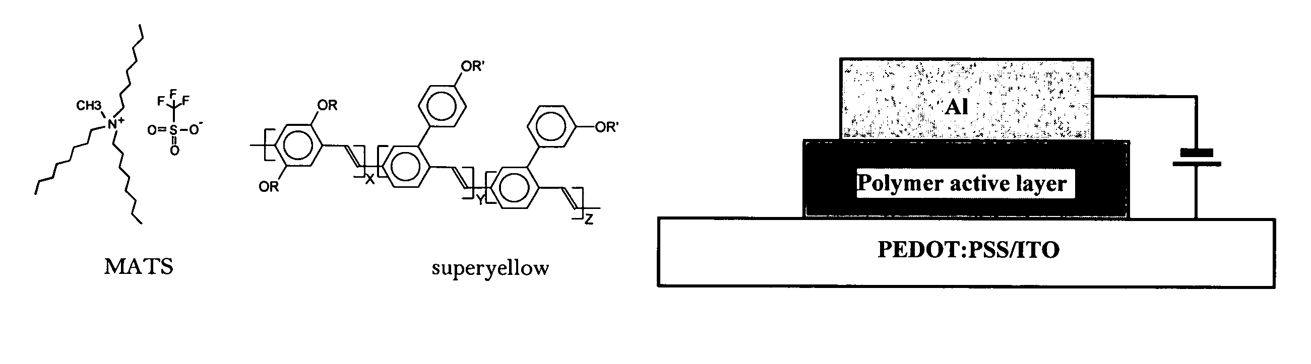
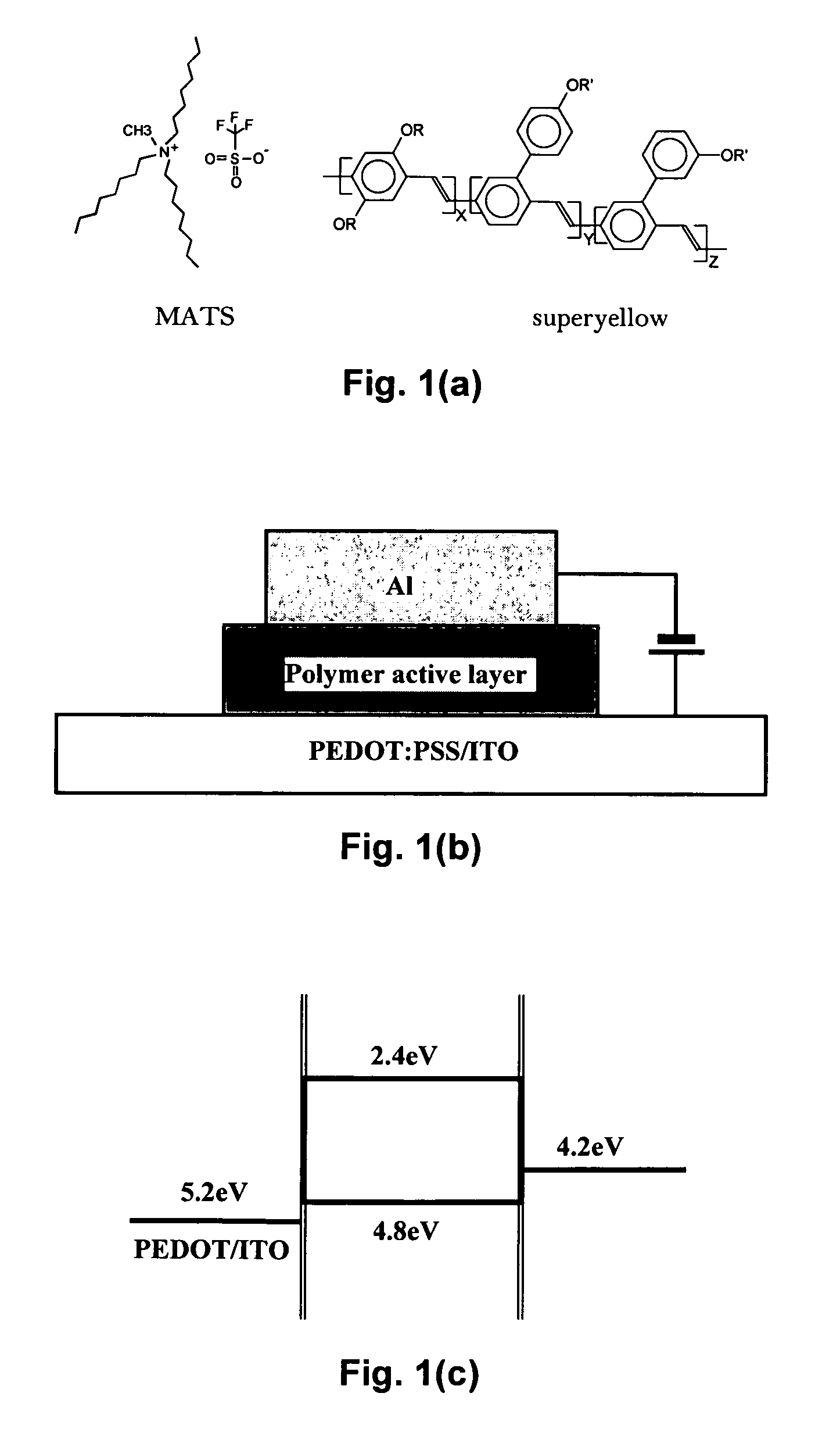
[0037]In the devices described here, we utilized the simplest sandwich structure for the device configuration with poly(3,4-ethylenedioxythiophene)-poly(styrene sulfonate) (PEDOT-PSS) coated indium-tin-oxide (ITO) glass as the anode and aluminum as the cathode. A soluble phenyl-substituted poly(para-phenylene vinylene) (PPV) copolymer (“superyellow” from Merck KGaA, Frankfurter Str. 250, 64293 Darmstadt, Germany) was selected as our host light-emitting polymer and an organic ionic liquid, methyltrioctylammonium trifluoromethanesulfonate (MATS) was used to introduce a dilute concentration of mobile ions into the emitting polymer layer. The molecular structures of MATS and superyellow are shown in FIG. 1(a).

[0038]In other embodiments, light emitting polymers other than phenyl-substituted poly(para-phenylene vinylene) (PPV) copolymer, and its derivatives substituted at various positions on the phenylene moiety, can be used including, but not limited to poly(2-methoxy-5-(2-ethylhexyloxy...


PUM

PropertyMeasurementUnit
Tgaaaaaaaaaa
melting temperatureaaaaaaaaaa

Abstract

Mixtures and light-emitting devices that incorporate such mixtures are disclosed in which a soluble phenyl-substituted poly(para-phenylene vinylene) (PPV) copolymer (“superyellow”) is used as the host light-emitting polymer and methyltrioctylammonium trifluoromethanesulfonate, an ionic liquid, is used to introduce a dilute concentration of mobile ions into the emitting polymer layer. These mixtures and devices incorporating them are able to combine some of the characteristics of polymer light emitting diodes (PLEDs) and polymer light-emitting electrochemical cells (PLECs).

Description

RELATED APPLICATIONS[0001]This application claims the benefit of U.S. Provisional Application No. 60 / 850227 filed on Oct. 5, 2006, which is incorporated herein by reference in its entirety.FIELD OF THE INVENTION[0002]The invention relates to polymer light-emitting devices.BACKGROUND OF THE INVENTION[0003]Polymer light-emitting devices have been divided into two general types: polymer light-emitting diodes (PLEDs) and polymer light-emitting electrochemical cells (PLECs) [1, 2, 3, 4, 5]. The advantages for PLEDs include fast response and relatively long operating lifetime (with proper packaging). However, low work function cathodes and / or thin interfacial layers (e.g. LiF) between the metal and the emitting polymer layer are required. In contrast, PLECs have relatively low turn-on voltages (approximately equal to the band gap of the luminescent semiconducting polymer), and low work function metals are not required.[0004]One of the serious disadvantages of PLECs, however, is the slow r...

Claims


Application Information

Patent Timeline
Patent Type & Authority Patents(United States)
IPC IPC(8): C08K5/19C08K5/3415C08K5/3445
CPCH01L51/5032C08K5/19H01L51/0038C08K5/42H10K85/114H10K50/135
Inventor SHAO, YANBAZAN, GUILLERMO C.HEEGER, ALAN J.
Owner RGT UNIV OF CALIFORNIA
Why Eureka
Try Eureka