
Communication apparatus, method, program, and recording medium

a technology of communication apparatus and recording medium, applied in the direction of transmission path sub-channel allocation, baseband system details, wireless communication, etc., can solve the problems of radio signal propagation loss and increase in radio frequency, and achieve the effect of reducing circuit scale and efficient demodulation of spatial multiplexed signal sequen

Active Publication Date: 2022-09-27
NEC CORP
View PDF17 Cites 0 Cited by
  • Summary
  • Abstract
  • Description
  • Claims
  • Application Information

AI Technical Summary

Benefits of technology

[0018]According to an example aspect of the present invention, it is possible to efficiently demodulate a spatially multiplexed signal sequence while attempting a reduction in circuit scale. Note that, according to the present invention, instead of or together with the above effects, other effects may be exerted.

Problems solved by technology

However, an increase in radio frequency increases propagation loss of radio signals.

Method used


Image

  • Communication apparatus, method, program, and recording medium
  • Communication apparatus, method, program, and recording medium
  • Communication apparatus, method, program, and recording medium

Examples


first example embodiment

3. First Example Embodiment

[0060]Next, a description will be given of a first example embodiment of the present invention with reference to FIGS. 5 and 6.

3.1. Configuration of Base Station

[0061]Next, with reference to FIG. 5, a description will be given of an example of a configuration of a base station 100 according to the first example embodiment. FIG. 5 is a block diagram illustrating an example of a schematic configuration of the base station 100 according to the first example embodiment. With reference to FIG. 5, the base station 100 includes a multi-element antenna 110, a storage section 120, and a processing section 130.

[0062](1) Multi-Element Antenna 110

[0063]The multi-element antenna 110 includes a plurality of antenna elements and configured to transmit and receive a signal wirelessly. For example, the multi-element antenna 110 receives a signal from a terminal apparatus and transmits a signal to the terminal apparatus.

[0064](2) Storage Section 120

[0065]The storage section...

example alterations

[0103]For example, the first weighting factor generation processing is more complex than the second weighting factor generation processing, which also requires a large amount of calculation. For this reason, even in a case of not using a multi-element antenna, it is possible to achieve a reduction in circuit scale as described above. Specifically, even in a case of N=M, it is possible to perform MIMO reception efficiently.

second example embodiment

4. Second Example Embodiment

[0104]Next, a description will be given of a second example embodiment of the present invention with reference to FIG. 7. The above-described first example embodiment is a concrete example embodiment, whereas the second example embodiment is a more generalized example embodiment.

4.1. Configuration of Communication Apparatus

[0105]First, with reference to FIG. 7, an example of a configuration of a communication apparatus 300 according to the second example embodiment will be described. FIG. 7 is a block diagram illustrating an example of a schematic configuration of the communication apparatus 300 according to the second example embodiment. With reference to FIG. 7, the communication apparatus 300 includes a first channel estimating unit 311, a first weight information generating unit 313, a synthesis processing unit 315, a second channel estimating unit 317, a second weight information generating unit 319, and a demodulation processing unit 321. Concrete o...


PUM


Abstract

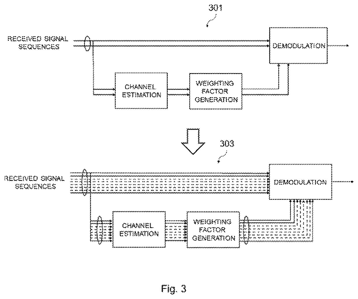
A communication apparatus 300 includes a first channel estimating unit 131 configured to perform a first channel estimation at a first frequency using a reference signal included in a signal sequence, a first weight information generating unit 133 configured to generate first weight information based on the first channel estimation, a synthesis processing unit 135 configured to perform weighted synthesis processing based on the first weight information, a second channel estimating unit 137 configured to perform a second channel estimation at a second frequency higher than the first frequency using a reference signal included in the signal sequence subjected to the weighted synthesis processing, a second weight information generating unit 139 configured to generate second weight information based on the second channel estimation, and a demodulation processing unit 141 configured to perform demodulation processing of the signal sequence subjected to the weighted synthesis processing based on the second weight information.

Description

CROSS REFERENCE TO RELATED APPLICATIONS[0001]This application is a National Stage of International Application No. PCT / JP2019 / 000508 filed Jan. 10, 2019, claiming priority based on Japanese Patent Application No. 2018-074406 filed Apr. 9, 2018, the entire disclosure of which is incorporated herein.BACKGROUNDTechnical Field[0002]The present invention relates to a communication apparatus, a method, a program, and a recording medium.Background Art[0003]It is desired for Long Term Evolution (LTE) systems, which are fourth-generation mobile communication systems, and New Radio (NR) systems, which are fifth-generation mobile communication systems, to achieve broadbandization of a frequency bandwidth and use a signal spatial multiplexing scheme, for the purpose of adopting to a rapidly advancing increase in transmission rate.[0004]To achieve broadbandization of a frequency bandwidth, the use of a high radio frequency band, such as a millimeter waveband, is effective. However, an increase i...

Claims


Application Information

Patent Timeline
Patent Type & Authority Patents(United States)
IPC IPC(8): H04L25/02H04L5/26H04B7/0413H04L5/00
CPCH04L25/0228H04B7/0413H04L5/0048H04W16/28H04L5/0051H04L25/022H04L25/0224H04L25/03891H04B7/0617H04B7/0837
Inventor IWASAKI, MOTOYA
Owner NEC CORP
Learn More