
Method and device for transmitting and receiving signal on basis of multiple antennas

a technology of transmitting and receiving signals, applied in multiplex communication, orthogonal multiplex, wireless communication, etc., to achieve the effect of efficiently demodulating symbols transmitted, increasing channel capacity, and effectively utilizing resources

Active Publication Date: 2017-09-19
SAMSUNG ELECTRONICS CO LTD
View PDF9 Cites 1 Cited by
  • Summary
  • Abstract
  • Description
  • Claims
  • Application Information

AI Technical Summary

Benefits of technology

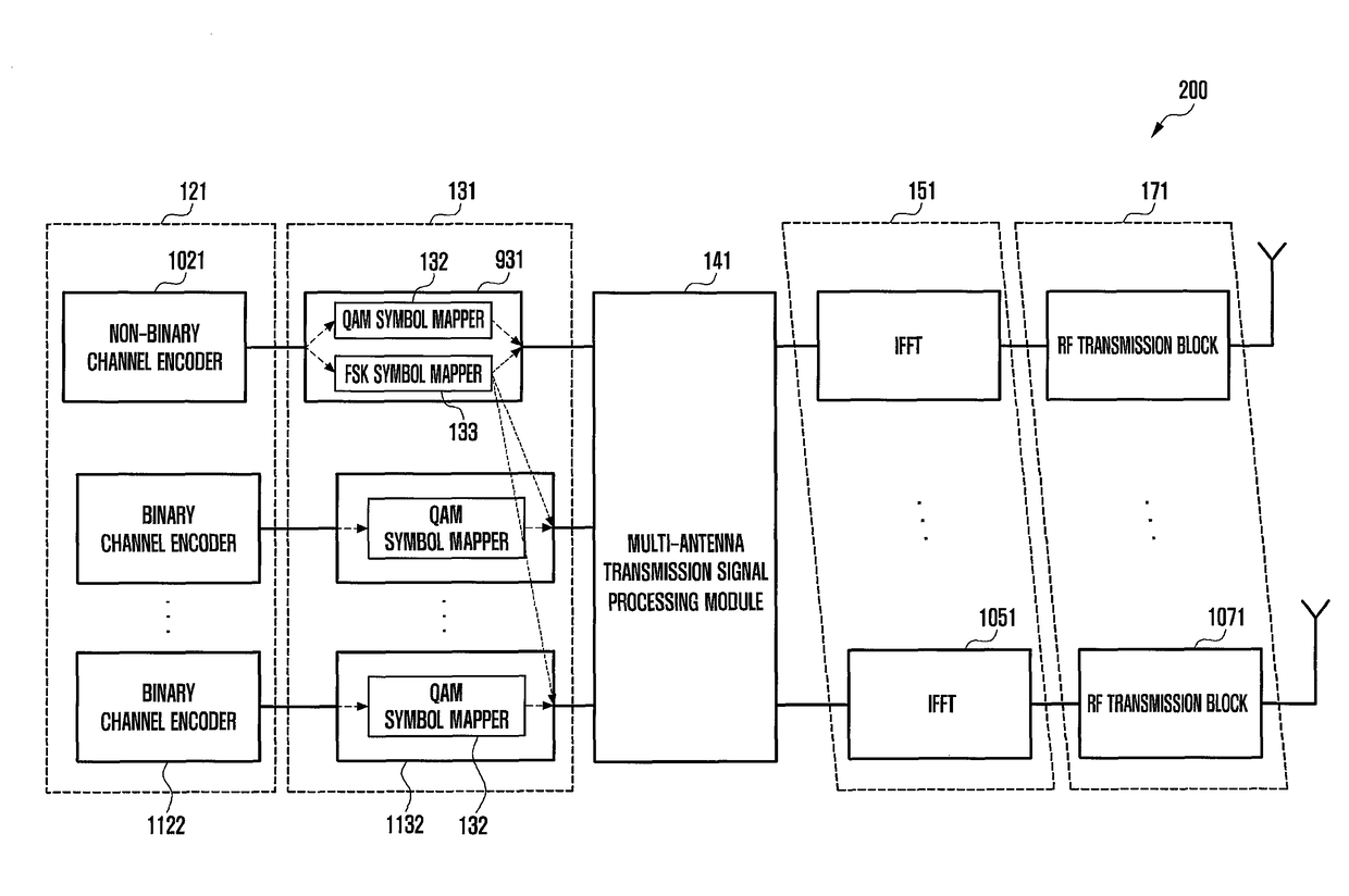
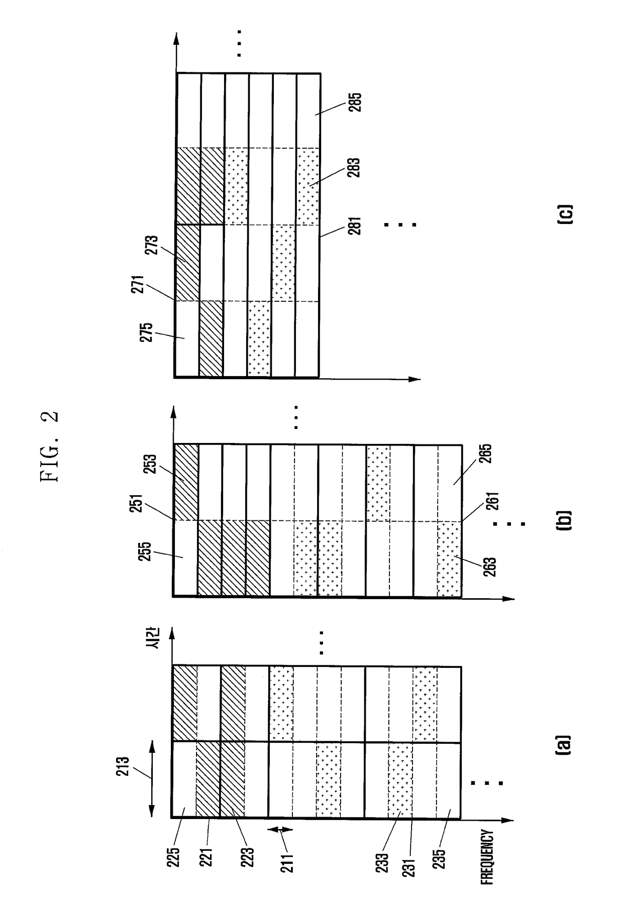
[0013]According to the aspects of the present invention, symbols corresponding to the multiple antennas are mapped to a frequency tone designated among the preset frequency tones and not mapped to the rest frequency tones, thereby obtaining an effect that the system may have an interference characteristic similar to the non-Gaussian form and channel capacity may be increased.
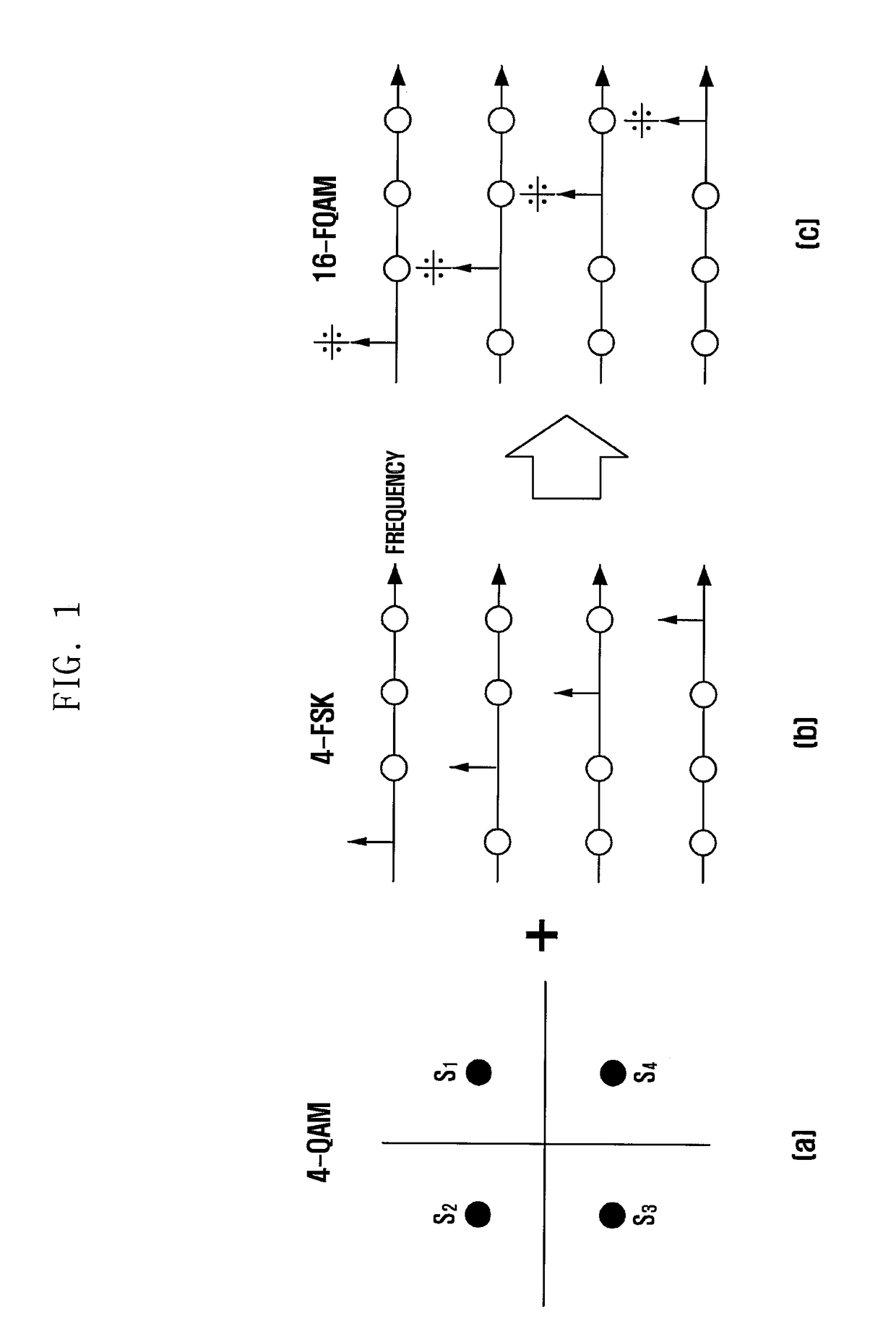
[0014]Further, in consideration of a frequency tone to which a symbol corresponding to the modulation mode in which the FSK and the QAM are combined, a frequency tone to which other symbol transmitted together through the multiple antennas is mapped is designated, thereby obtaining an effect of providing a plan for more effectively utilizing resources.
[0015]Further, tone location information of an activated tone carrying a QAM signal of a symbol corresponding to the modulation mode in which the FSK and the QAM are combined is detected, and at least one of demodulation of a plurality of symbols or acquisition of a bit stream based on the tone location information is performed, thereby obtaining an effect of providing a plan for efficiently demodulating symbols transmitted through the multiple antennas.

Problems solved by technology

In the wireless communication system, users having a low signal-to-noise ratio (SNR) or users at a cell edge remote from a cell center that have a low carrier-to-interference and noise ratio (CINR) due to interference from a base station of an adjacent cell may be offered with limited quality of services.

Method used


Image

  • Method and device for transmitting and receiving signal on basis of multiple antennas
  • Method and device for transmitting and receiving signal on basis of multiple antennas
  • Method and device for transmitting and receiving signal on basis of multiple antennas

Examples


Embodiment Construction

[0049]Hereinafter, a method for manufacturing and using a device for transmitting and receiving a signal on the basis of multiple antennas according to the present invention will be described in detail. Terms “unit”, “module”, or the like, described in the specification means a unit of processing at least one function or operation and may be implemented by hardware or software or a combination of hardware and software.

[0050]An electronic device according to an embodiment of the present invention may include at least one of a transmitting device and a receiving device. The electronic device may be implemented in various forms. For example, the electronic device described in the present specification may include a device having a communication function such as a base station, an access point, a portable terminal, a computer, a communication card, a modem chip, a dongle, or the like, or a device capable of providing the communication function by being combined with other device, but is...


PUM


Abstract

A method and a device for transmitting and receiving a signal on the basis of multiple antennas are provided.A transmitting device may include a radio frequency (RF) module transmitting a quadrature amplitude modulation (QAM) signal of a first symbol corresponding to a hybrid frequency shift keying and quadrature amplitude modulation (FQAM) mode and transmitting a QAM signal of a second symbol corresponding to a QAM mode through a second antenna; and a modulation module mapping the QAM signal of the first symbol to one frequency tone among the preset number of frequency tones according to a frequency shift keying (FSK) signal of the first symbol and mapping the second symbol to the frequency tone to which the first symbol is mapped.

Description

TECHNICAL FIELD[0001]The present invention relates to a method and a device for transmitting and receiving a signal using multiple antennas.BACKGROUND ART[0002]A wireless communication system has been developed for supporting higher data transmission rate in order to satisfy a continuously increasing demand for wireless data traffic. For example, technologies for the wireless communication system capable of improving spectral efficiency and increasing channel capacity on the basis of a communication technology such as an orthogonal frequency division multiplexing (hereinafter, referred to as OFDM) scheme and multiple input multiple output (MIMO) transmission and reception have been developed in order to increase data transmission rate.[0003]In the wireless communication system, users having a low signal-to-noise ratio (SNR) or users at a cell edge remote from a cell center that have a low carrier-to-interference and noise ratio (CINR) due to interference from a base station of an ad...

Claims


Application Information

Patent Timeline
Patent Type & Authority Patents(United States)
IPC IPC(8): H04L27/36H04L27/32H04J11/00H04L27/34H04L27/38H04L27/12H04B7/06H04L27/10H04L27/26
CPCH04L27/366H04B7/06H04J11/0059H04L27/10H04L27/12H04L27/32H04L27/34H04L27/364H04L27/367H04L27/38H04L27/2601H04L5/0091H04L27/36H04W72/23
Inventor KIM, JAEWONPARK, JEONGHOSAGONG, MINLIM, CHIWOOJEONG, SURYONGHONG, SUNGNAM
Owner SAMSUNG ELECTRONICS CO LTD
Learn More