Relay node and relay method

a relay and node technology, applied in multiplex communication, frequency-division multiplex, site diversity, etc., can solve problems such as channel capacity reduction, and achieve the effect of improving the channel capacity of the entire communication system, and improving the channel capacity of the entire system

Inactive Publication Date: 2008-02-28
NTT DOCOMO INC
View PDF3 Cites 23 Cited by
  • Summary
  • Abstract
  • Description
  • Claims
  • Application Information

AI Technical Summary

Benefits of technology

[0010]According to such a relay node and a relay method, at least either the backward channel transmission quality or the forward channel transmission quality is measured, a relay method to be applied in the relay node is selected in accordance with the measured transmission quality, and the transmission signal is multiplied by a conversion matrix corresponding to the selected relay method, whereby the transmission signal received from the source node is converted to a relay signal, and then this relay signal is transmitted to the destination node. Accordingly, a relay method that is suitable for the backward channel transmission quality or the forward channel transmission quality of each relay node is selected, so that the transmission signal is processed using this relay method. Therefore, the channel capacity is increased when each relay node is relayed, improving the channel capacity of the entire communication system effectively.
[0011]It is preferred that the relay node further have matrix calculation means for performing matrix calculation on the relay signal obtained by conversion by the converting means, so that coherent combining can be performed among the multiple relay methods on the destination node side, and that the transmitting means transmit the relay signal on which the matrix calculation is performed by the matrix calculation means. In this case, when a relay signal is received from each of multiple relay nodes in the destination node, the relay signals received from the respective relay nodes are coherently combined, thus the channel capacity of the entire system can be further improved.
[0012]Furthermore, it is preferred that the relay node further have determination means for determining whether or not to relay the transmission signal to the destination node, in accordance with at least either the backward channel transmission quality or the forward channel transmission quality measured by the measuring means, and that the transmitting means transmit the relay signal when the determination means determines to relay the transmission signal. In this manner, it is determined whether or not to relay the transmission signal by means of the relay node in accordance with the backward channel transmission quality or the forward channel transmission quality, thus it is possible to prevent the relay node from performing unwanted signal relay when the channel capacity is not ensured.
[0013]Moreover, it is preferred that the measuring means measure both the backward channel transmission quality and the forward channel transmission quality, that the selecting means select, in accordance with the backward channel transmission quality and the forward channel transmission quality that are estimated by the measuring means, a relay method from among a QR-P-QR method for performing QR decomposition on each of the backward and forward channels, a QR-P-ZF method for performing QR decomposition and then zero-forcing (ZF) on each of the backward and forward channels, and ZF-P-QR method for performing zero-forcing (ZF) and then QR decomposition on each of the backward and forward channels, and that, when the QR-P-ZF method is selected by the selecting means, the matrix calculation means perform matrix calculation such that the order of rows in an output matrix of the converting means is inverted, and when the ZF-P-QR method is selected by the selecting means, the matrix calculation means perform matrix calculation such that the order of columns in the output matrix of the converting means is inverted. With this configuration, the proper relay method is selected from among the QR-P-QR method, QR-P-ZF method and ZF-P-QR method on the basis of the backward channel transmission quality and forward channel transmission quality, and the matrix calculation is performed on the relay signal in accordance with the selected relay method so that coherent combining can be performed in the destination node. Consequently, the channel capacity of the entire system can be improved effectively.
[0014]In addition, it is preferred that the measuring means measure both the backward channel transmission quality and the forward channel transmission quality, and that the selecting means select the relay method in accordance with a ratio between the backward channel transmission quality and the forward channel transmission quality that are measured by the measuring means. In this case, since the characteristics of the channel capacity of each of the QR-P-QR method, QR-P-ZF method and ZF-P-QR method rely largely on the ratio between the backward channel transmission quality and the forward channel transmission quality, the channel capacity of the entire system can be improved more reliably.
[0015]According to the present invention, the channel capacity of the entire communication system can be improved in accordance with the transmission quality of the channels of each node.

Problems solved by technology

Therefore, if all of relay nodes uniformly select a relay method when they have different channel transmission quality, it becomes impossible to ensure that an appropriate relay method is always selected in the entire communication system, causing reduction in the channel capacity.

Method used


Image

  • Relay node and relay method
  • Relay node and relay method
  • Relay node and relay method

Examples


Embodiment Construction

[0025]Preferred embodiments of the relay node and relay method of the present invention will be described hereinafter in detail with reference to the drawings. It should be noted in the descriptions of the drawings that the same reference numerals are used to indicate the same elements, thus the overlapping explanations are omitted accordingly.

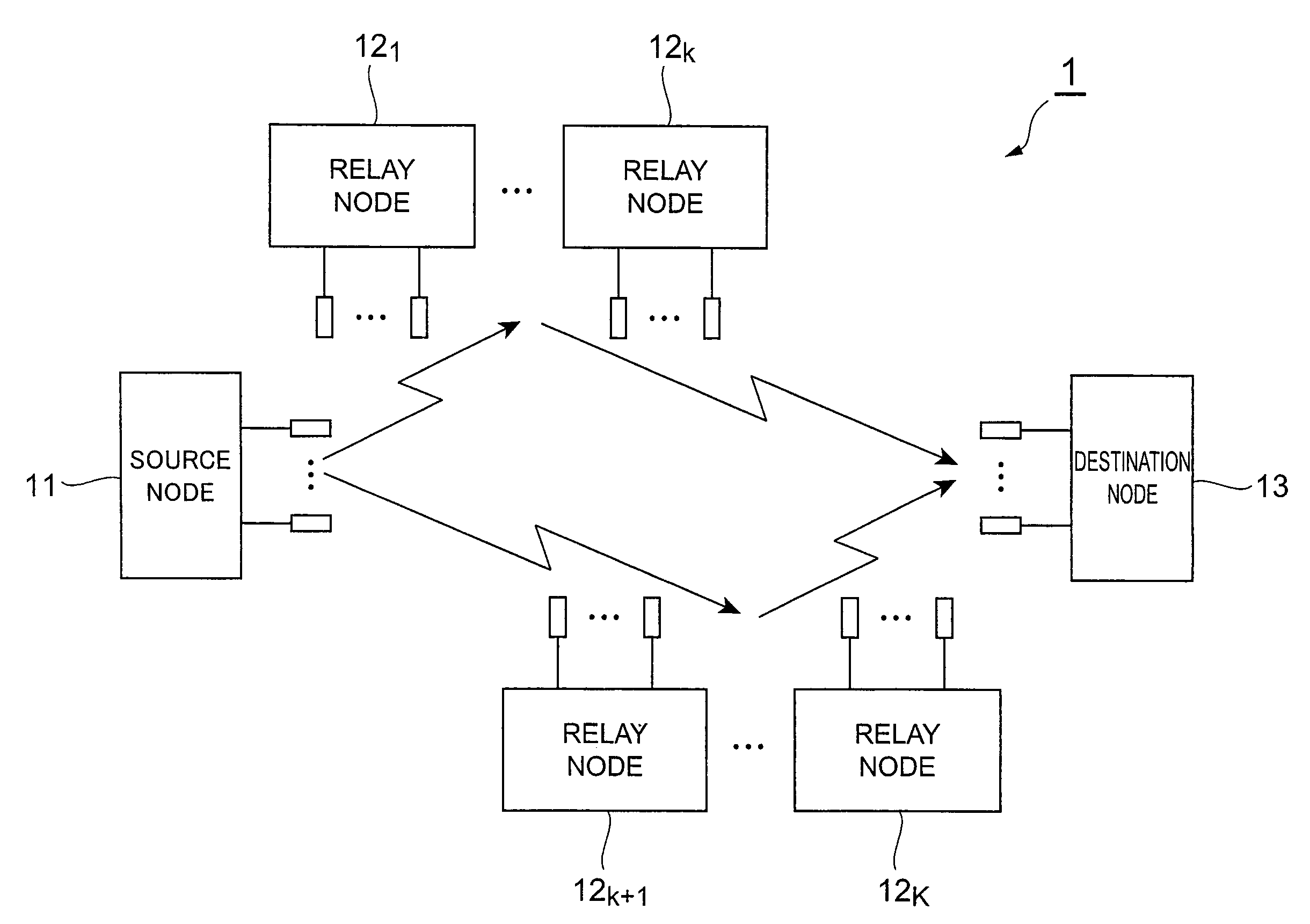
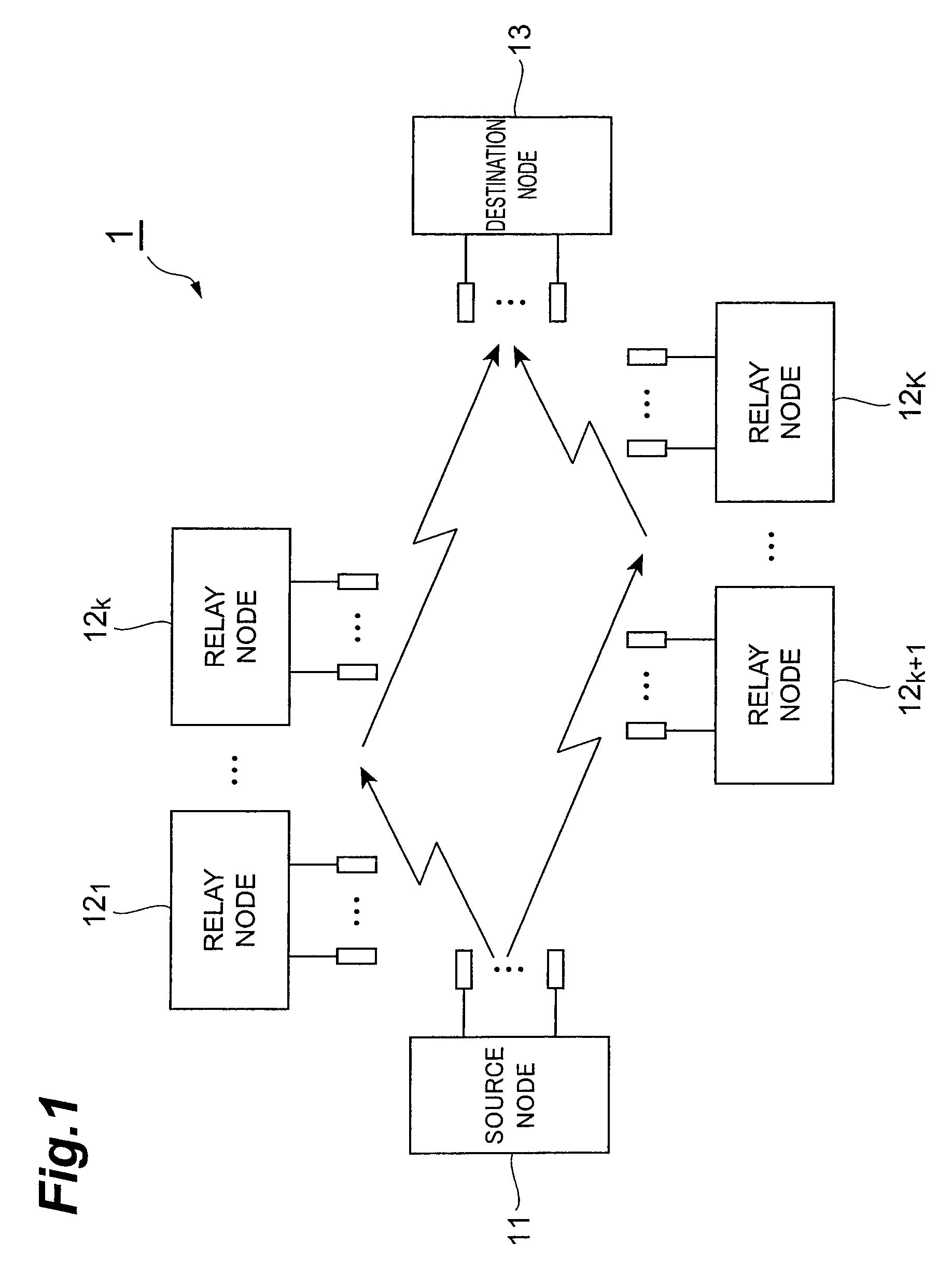
[0026]FIG. 1 is a diagram showing the configuration of a communication system 1 according to a preferred embodiment of the present invention. This communication system 1 is a system that uses a multiple-input multiple-output (MIMO) system to transmit a radio signal from a source node to a destination node, and is constituted by a source node 11, K number of (K is an integer of 1 or more) relay nodes 121, . . . , 12k, 12k+1, . . . 12K, and a destination node 13.

[0027]In this communication system 1, once a radio signal is transmitted from the source node 11 to the destination node 13, the relay nodes 121, . . . , 12k, 12k+1, . . . 12K can relay ...


PUM


Abstract

To improve the channel capacity of an entire communication system in accordance with transmission quality of the channels of each node. A relay node has: a receiving section that receives a received signal from a source node; a channel estimation section that measures SNR of a backward channel between the source node and the relay node, and SNR of a forward channel between the relay node and a destination node; a relay selecting section that selects, from among a QR-P-ZF method, a QR-P-QR method and a ZF-P-QR method, a relay method of the relay node in accordance with the ratio between the SNRs of the backward and forward channels; a relay signal processing section that multiplies the received signal by a transmission weight matrix corresponding to the selected relay method, and thereby converts the received signal to a relay signal; and a transmitting section that transmits the relay signal to the destination node.

Description

BACKGROUND OF THE INVENTION[0001]1. Field of the Invention[0002]The present invention relates to a relay node and a relay method for relaying a radio signal using a multiple-input multiple-output (MIMO) system.[0003]2. Related Background Art[0004]In recent years, a MIMO multihop system, which is a combination of a multihop system and a MIMO system, is getting attention as a technology for relaying radio signals. In the multihop system, signals are transmitted from a source node, which is the source of the signals, to a destination node, which is the destination of the signals, via 1 or more relay nodes located between the source node and the destination node. This system has advantages that the range where signals can be received is expanded by relaying signals, that the signal transmittable areas are not theoretically limited, and that a wireless network can be established quickly. The MIMO system, meanwhile, is a communication system in which multiple transmitting antennas and rec...

Claims


Application Information

Patent Timeline
Patent Type & Authority Applications(United States)
IPC IPC(8): H04B7/14H04J99/00
CPCH04B7/022H04B7/0413H04L2001/0097H04B7/2606H04L1/20H04B7/155
Inventor ASAI, TAKAHIROYOSHINO, HITOSHISHI, HUI
Owner NTT DOCOMO INC
Why Eureka
Try Eureka