Apparatus and method for demodulating input signal modulated from reference signal and data signal
a technology of reference signal and input signal, applied in the field of apparatus and methods for demodulating input signal modulated from reference signal and data signal, can solve the problem of difficulty in reducing the cost of conventional apparatus and methods for demodulating stw signal in the bd, and achieve the effect of efficient demodulation of stw signal
- Summary
- Abstract
- Description
- Claims
- Application Information
AI Technical Summary
Benefits of technology
Problems solved by technology
Method used
Image
Examples
first embodiment
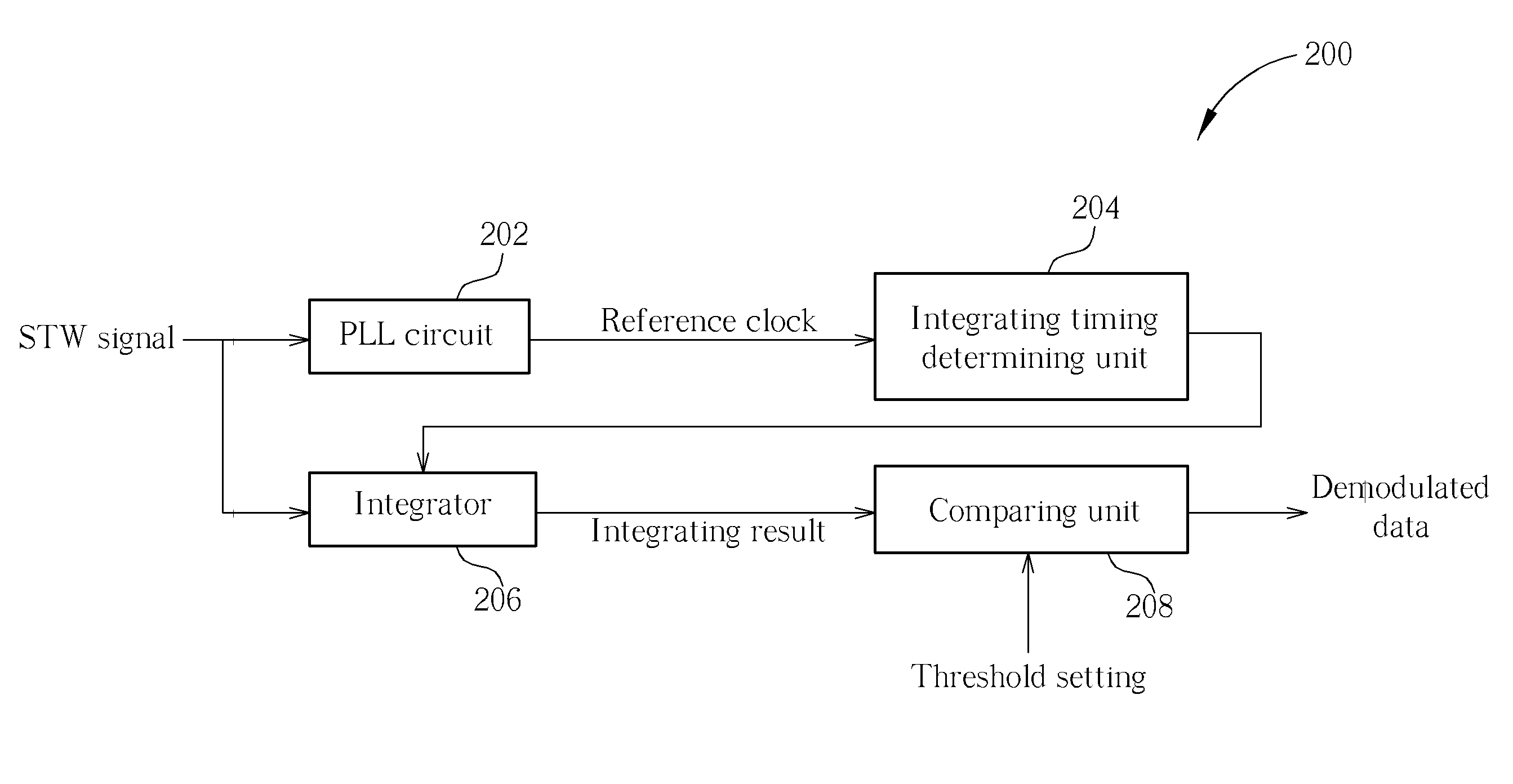
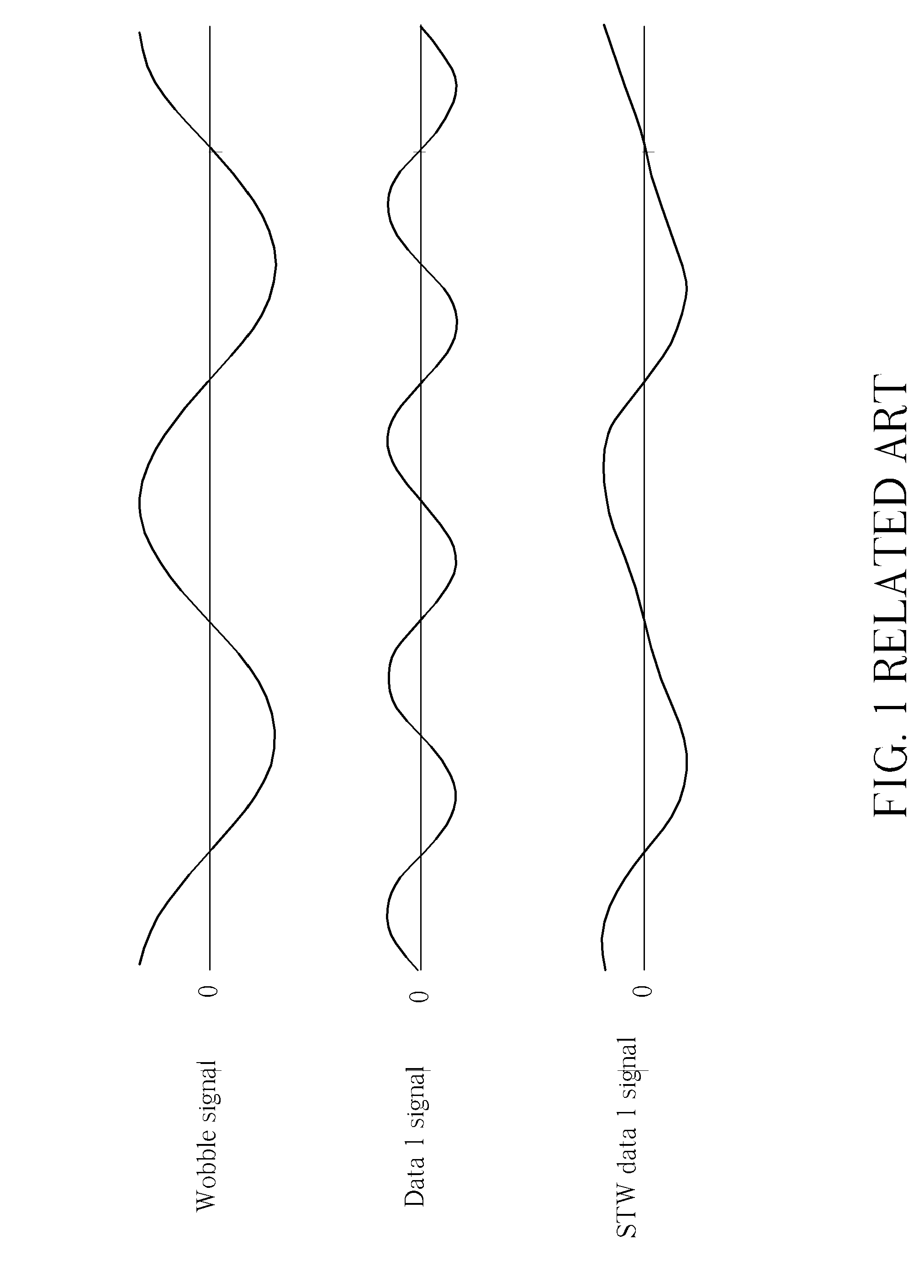
[0029]Please refer to FIG. 3, FIG. 4, and FIG. 5 together. FIG. 3 shows a simplified block diagram of a demodulating apparatus 200 for demodulating a saw tooth wobble (STW) signal modulated from a wobble signal and a data signal in a BD (Blu-ray Disk) (not shown) according to the present invention. FIG. 4 is a simplified diagram showing how the present invention method demodulates an STW signal modulated from the wobble signal and a data 1 signal (i.e. an STW data 1 signal) by performing an integrating operation according to the first embodiment shown in FIG. 3.
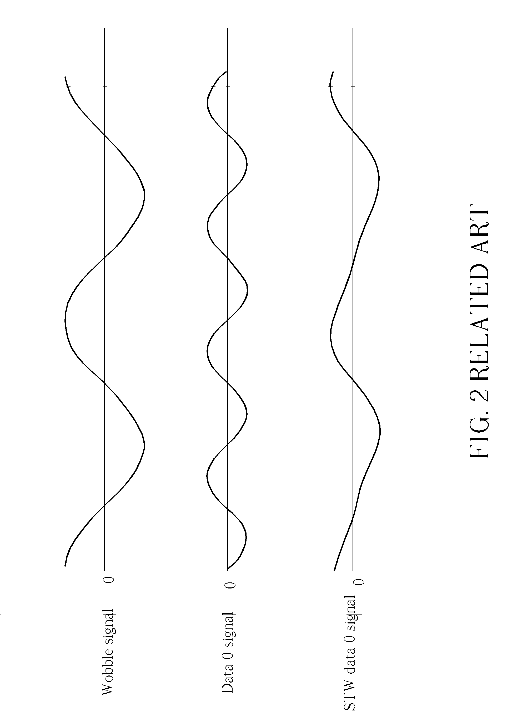
[0030]FIG. 5 is a simplified diagram showing how the present invention method demodulates another STW signal modulated from the wobble signal and a data 0 signal (i.e. an STW data 0 signal) by performing an integrating operation according to the first embodiment shown in FIG. 3. There is a phase difference of 180 degrees between the data 1 signal and the data 0 signal.
[0031]As shown in FIG. 3, the exemplary demodulating appar...
fifth embodiment
[0080]Please refer to FIG. 18. FIG. 18 shows a simplified block diagram of a demodulating apparatus 700 for demodulating the STW signal modulated from the wobble signal and the data signal in the BD according to the present invention. As shown in FIG. 18, the demodulating apparatus 700 includes a PLL circuit 702, an adding timing determining unit 704, a first adder 706, a second adder 707, and a comparing unit 708. The PLL circuit 702 is coupled to the adding timing determining unit 704 and utilized for performing a clock recovering operation according to the STW signal and generating a reference clock locked to the wobble signal. The adding timing determining unit 704 is utilized for determining a plurality of first adding timing points of changing different adding modes for the first adder 706 and a plurality of second adding timing points of changing different adding modes for the second adder 707 according to the reference clock, wherein a phase difference between the first calc...
sixth embodiment
[0082]Please refer to FIG. 19. FIG. 19 shows a simplified block diagram of a demodulating apparatus 800 for demodulating the STW signal modulated from the wobble signal and the data signal in the BD according to the present invention. As shown in FIG. 19, the demodulating apparatus 800 includes a PLL circuit 802, an adding timing determining unit 804, a first adder 806, a second adder 807, and a comparing unit 808. The PLL circuit 802 is coupled to the adding timing determining unit 804 and utilized for performing a clock recovering operation according to the STW signal and generating a reference clock locked to the wobble signal. The adding timing determining unit 804 is utilized for determining a plurality of first adding timing points of changing different adding modes for the first adder 806 and a plurality of second adding timing points of changing different adding modes for the second adder 807 according to the reference clock, wherein a phase difference between the first calc...
PUM
| Property | Measurement | Unit |
|---|---|---|
| included angle | aaaaa | aaaaa |
| included angle | aaaaa | aaaaa |
| frequency | aaaaa | aaaaa |
Abstract
Description
Claims
Application Information
 - R&D
- Intellectual Property
- Life Sciences
- Materials
- Tech Scout
- Unparalleled Data Quality
- Higher Quality Content
- 60% Fewer Hallucinations
Browse by: Latest US Patents, China's latest patents, Technical Efficacy Thesaurus, Application Domain, Technology Topic, Popular Technical Reports.
© 2025 PatSnap. All rights reserved.Legal|Privacy policy|Modern Slavery Act Transparency Statement|Sitemap|About US| Contact US: help@patsnap.com


