Apparatus and method for demodulating input signal modulated from reference signal and data signal

a technology of reference signal and input signal, applied in the field of apparatus and methods for demodulating input signal modulated from reference signal and data signal, can solve the problem of difficulty in reducing the cost of conventional apparatus and methods for demodulating stw signal in the bd, and achieve the effect of efficient demodulation of stw signal

Active Publication Date: 2010-09-07
MEDIATEK INC
View PDF9 Cites 0 Cited by
  • Summary
  • Abstract
  • Description
  • Claims
  • Application Information

AI Technical Summary

Benefits of technology

[0004]It is therefore one of the objectives of the present invention to provide an apparatus and method for efficiently demodulating an STW signal comprising a wobble signal and a data signal, to solve the above problem.

Problems solved by technology

However, the band-pass filter and the multiplier are very expensive, and therefore it is quite difficult to reduce the cost of the conventional apparatus and methods for demodulating the STW signal in the BD.

Method used


Image

  • Apparatus and method for demodulating input signal modulated from reference signal and data signal
  • Apparatus and method for demodulating input signal modulated from reference signal and data signal
  • Apparatus and method for demodulating input signal modulated from reference signal and data signal

Examples


first embodiment

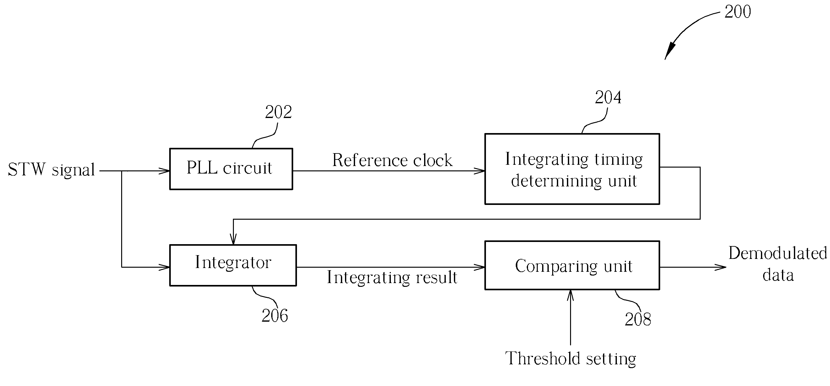
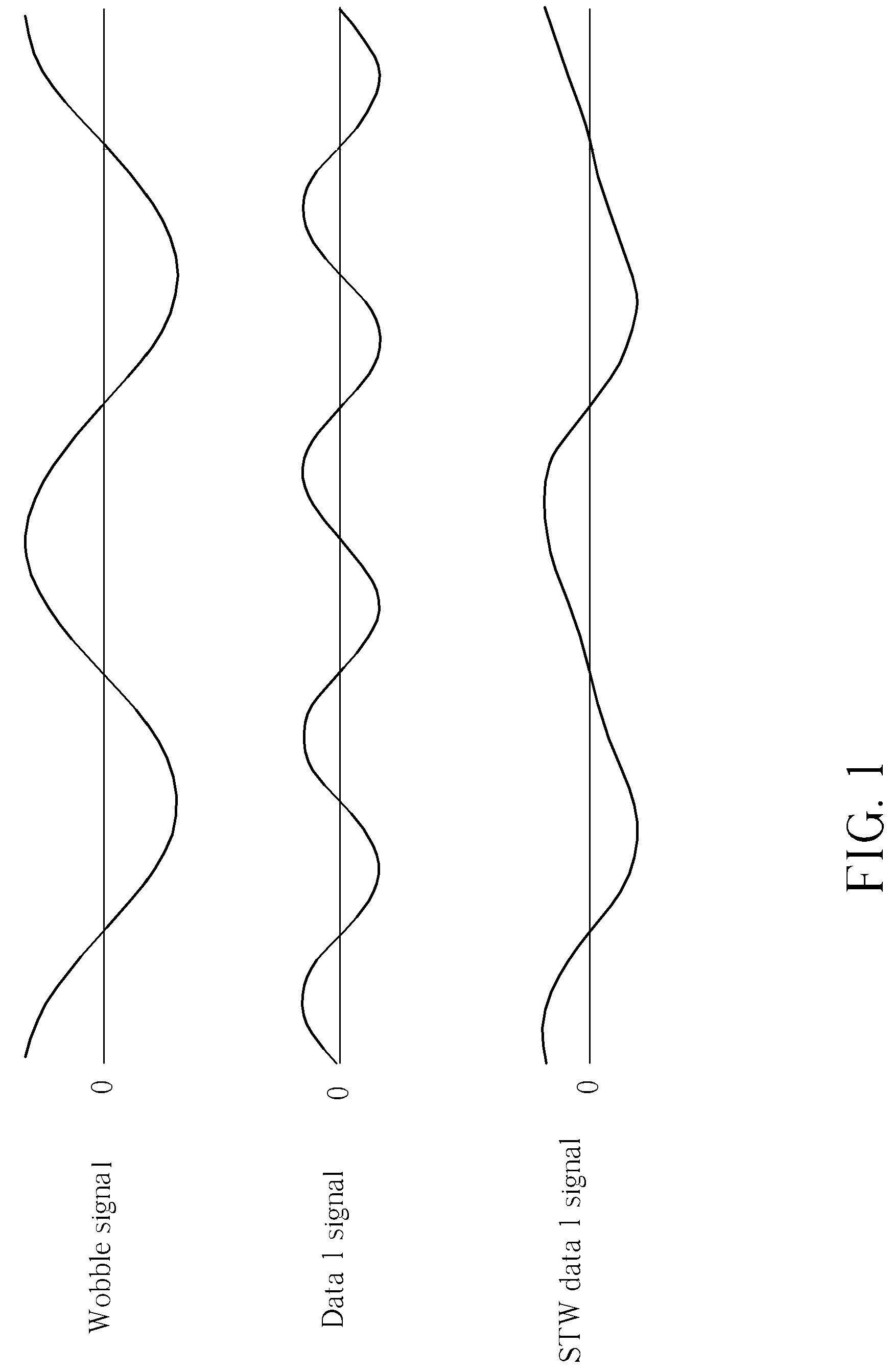
[0029]Please refer to FIG. 3, FIG. 4, and FIG. 5 together. FIG. 3 shows a simplified block diagram of a demodulating apparatus 200 for demodulating a saw tooth wobble (STW) signal modulated from a wobble signal and a data signal in a BD (Blu-ray Disk) (not shown) according to the present invention. FIG. 4 is a simplified diagram showing how the present invention method demodulates an STW signal modulated from the wobble signal and a data 1 signal (i.e. an STW data 1 signal) by performing an integrating operation according to the first embodiment shown in FIG. 3.

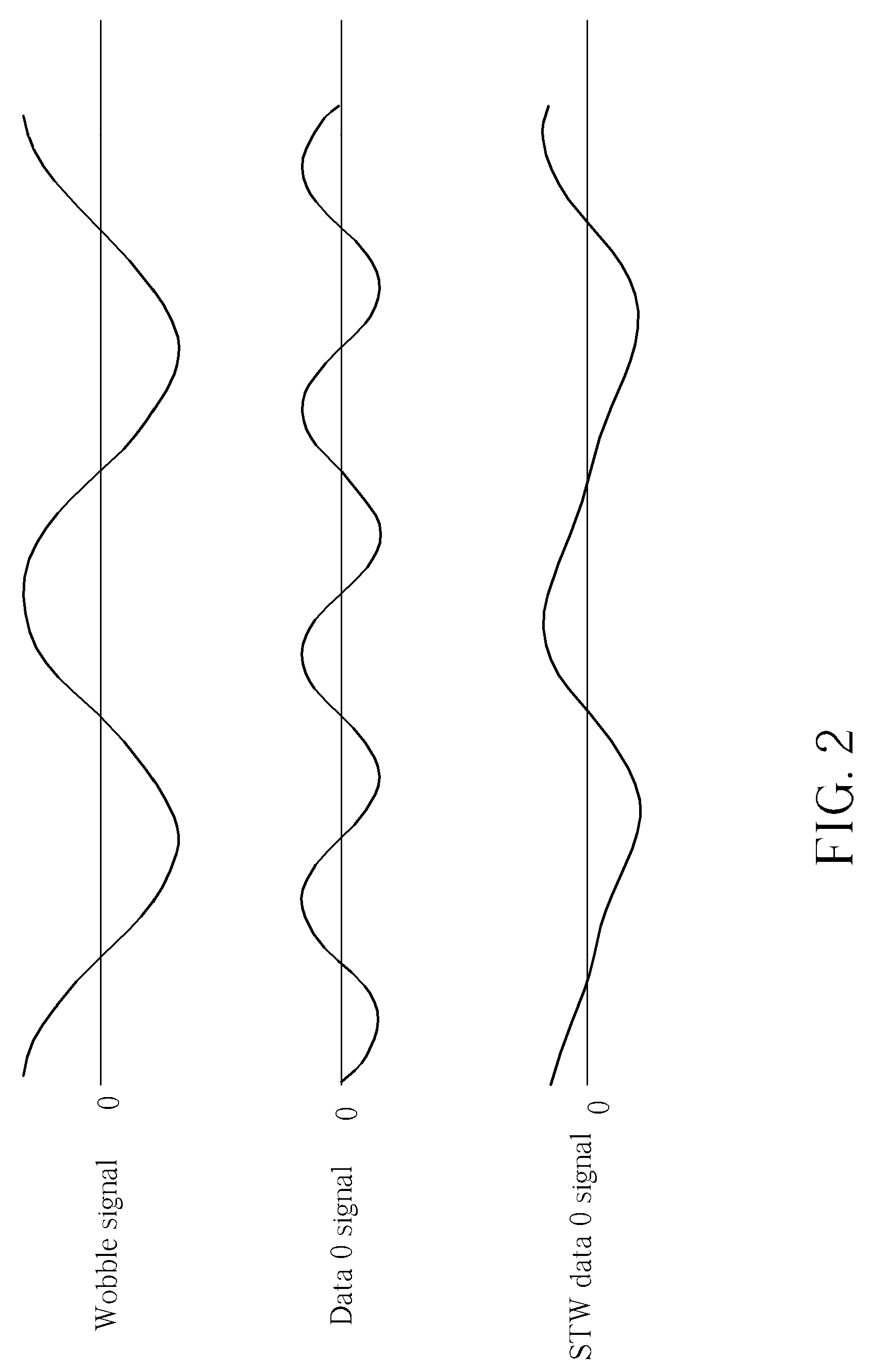
[0030]FIG. 5 is a simplified diagram showing how the present invention method demodulates another STW signal modulated from the wobble signal and a data 0 signal (i.e. an STW data 0 signal) by performing an integrating operation according to the first embodiment shown in FIG. 3. There is a phase difference of 180 degrees between the data 1 signal and the data 0 signal.

[0031]As shown in FIG. 3, the exemplary demodulating appar...

fifth embodiment

[0082]Please refer to FIG. 18. FIG. 18 shows a simplified block diagram of a demodulating apparatus 700 for demodulating the STW signal modulated from the wobble signal and the data signal in the BD according to the present invention. As shown in FIG. 18, the demodulating apparatus 700 includes a PLL circuit 702, an adding timing determining unit 704, a first adder 706, a second adder 707, and a comparing unit 708. The PLL circuit 702 is coupled to the adding timing determining unit 704 and utilized for performing a clock recovering operation according to the STW signal and generating a reference clock locked to the wobble signal. The adding timing determining unit 704 is utilized for determining a plurality of first adding timing points of changing different adding modes for the first adder 706 and a plurality of second adding timing points of changing different adding modes for the second adder 707 according to the reference clock, wherein a phase difference between the first calc...

sixth embodiment

[0084]Please refer to FIG. 19. FIG. 19 shows a simplified block diagram of a demodulating apparatus 800 for demodulating the STW signal modulated from the wobble signal and the data signal in the BD according to the present invention. As shown in FIG. 19, the demodulating apparatus 800 includes a PLL circuit 802, an adding timing determining unit 804, a first adder 806, a second adder 807, and a comparing unit 808. The PLL circuit 802 is coupled to the adding timing determining unit 804 and utilized for performing a clock recovering operation according to the STW signal and generating a reference clock locked to the wobble signal. The adding timing determining unit 804 is utilized for determining a plurality of first adding timing points of changing different adding modes for the first adder 806 and a plurality of second adding timing points of changing different adding modes for the second adder 807 according to the reference clock, wherein a phase difference between the first calc...


PUM

PropertyMeasurementUnit
included angleaaaaaaaaaa
frequencyaaaaaaaaaa

Abstract

An apparatus and method for demodulating an input signal modulated from a reference signal and a data signal are disclosed. The apparatus includes a determining unit, a first calculating unit, and a comparing unit. The determining unit is utilized for determining a plurality of first calculating timings of changing different calculating modes according to the input signal. The first calculating unit is coupled to the determining unit and utilized for generating a first calculating result of the input signal according to the first calculating timings and the calculating modes thereof. The comparing unit is coupled to the first calculating unit and utilized for generating a comparing result according to the first calculating result of the input signal and a threshold setting, and for outputting a demodulated data of the input signal according to the comparing result.

Description

BACKGROUND[0001]The present invention relates to an apparatus and method for demodulating an input signal modulated from a reference signal and a data signal, and more particularly, to an apparatus and method for efficiently demodulating a saw tooth wobble (STW) signal modulated from a wobble signal and a data signal in a BD (Blu-ray Disk).[0002]In general, the STW signal in the BD is formed by a sinusoidal signal having a wobble frequency (i.e. the wobble signal) added to another sinusoidal signal having a data frequency (i.e. the data signal), wherein the data frequency is twice as greater as the wobble frequency. Please refer to FIG. 1 in conjunction with FIG. 2. FIG. 1 is a simplified diagram showing an STW signal modulated from the wobble signal and a data 1 signal having a first data frequency (i.e. an STW data 1 signal), and FIG. 2 is a simplified diagram showing another STW signal modulated from the wobble signal and a data 0 signal having a second data frequency (i.e. an ST...

Claims


Application Information

Patent Timeline
Patent Type & Authority Patents(United States)
IPC IPC(8): G11B7/00
CPCG11B20/10037G11B20/10222G11B20/10425G11B20/1217G11B20/1403G11B7/0053G11B2020/1239G11B2020/1268G11B2220/2541
Inventor LIN, YU-HSUANCHOU, SHU-HUNGLIU, PI-HAI
Owner MEDIATEK INC
Why Eureka
Try Eureka