

Novel device and method for treatment of congestive heart failure
a congestive heart failure and new technology, applied in the field of congestive heart failure devices and methods, can solve the problems of significant mortality and morbidity
- Summary
- Abstract
- Description
- Claims
- Application Information
AI Technical Summary
Problems solved by technology
Method used
Image

Examples
Embodiment Construction
[0014] The following description is provided to enable any person skilled in the art to make and use the invention, and sets forth the best modes contemplated by the inventor of carrying out his invention. Various modifications, however, will remain readily apparent to those skilled in the art, since the generic principles of the present invention have been defined herein specifically to provide for improved devices for constraining the heart and an improved method therefor.
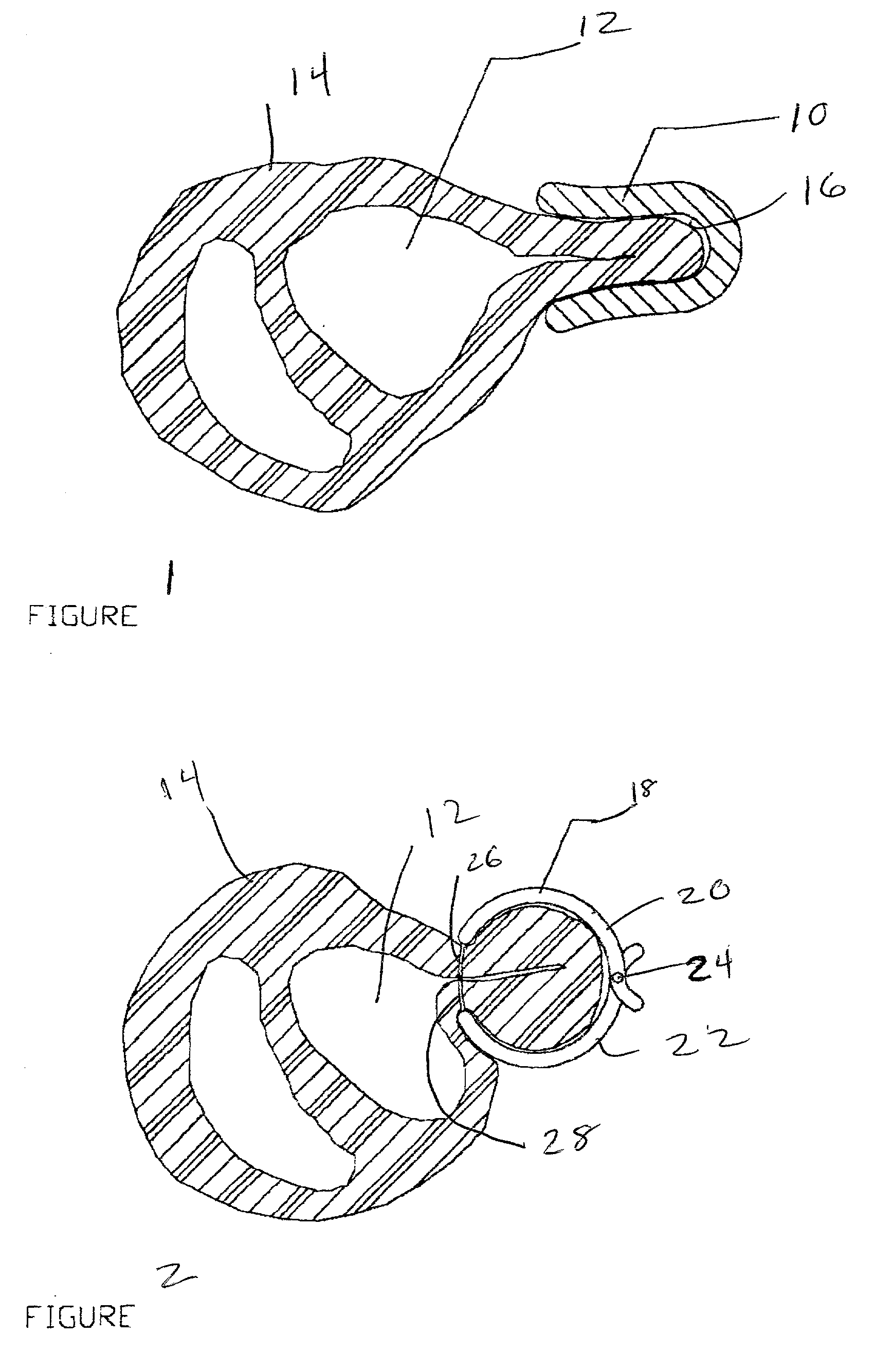
[0015] FIG. 1 shows a device 10 comprised of a clamp made from stainless steel, or the like. The device 10 is placed over and constrains a portion of a left ventricle 12 of a heart 14 so as to pinch or constrain the portion of the heart wall held between an open area 16 in the device 10. The device 10 may be of any desired length and include closed or open ends.
[0016] FIG. 2 shows a further device 18 comprised of a clamp having two movable pieces or segments 20, 22, secured together at a spring joint 24. Before t...
PUM
 Abstract
Description
Claims
Application Information