Reflector, method for the production of reflector, and internal-lighting display device

a technology of reflector and display device, which is applied in the direction of display devices, lighting and heating equipment, instruments, etc., can solve the problems of difficult to increase the internal-lighting luminance of the retro-reflective sheet surface (light-emitting surface) of the conventional internal-lighting display device having the flat backside of the reflective sheet, and difficult to increase the internal-lighting luminance of the conventional internal-lighting display devi

Inactive Publication Date: 2001-09-13
3M INNOVATIVE PROPERTIES CO
View PDF0 Cites 44 Cited by
  • Summary
  • Abstract
  • Description
  • Claims
  • Application Information

AI Technical Summary

Problems solved by technology

However, it is difficult to increase a luminance on retroreflective sheet surfaces (light-emitting surfaces) of conventional internal-lighting devices with internal light sources.
In particular, it is very difficult to increase the internal-lighting luminance in a wide observation angle range.
Therefore, it is difficult to increase the internal-lighting luminance of a conventional internal-lighting display device having the flat backside of the reflective sheet.
When P is less than 4 mm, the internal-lighting luminance may decrease, and the reflection properties in relation to light at a high entrance angle may not be improved.
When P is too large, the internal-lighting luminance at a relatively high observation angle is not improved so that the internal-lighting luminance may not be increased in a wide observation angle range.
Furthermore, the improving effect on the reflection properties at a high entrance angle may deteriorate.
When h is less than 0.5 mm, the internal-lighting luminance in a wide observation angle range may not increase, and the reflection properties in relation

Method used


Image

  • Reflector, method for the production of reflector, and internal-lighting display device
  • Reflector, method for the production of reflector, and internal-lighting display device

Examples


example 1

[0118] Example 1

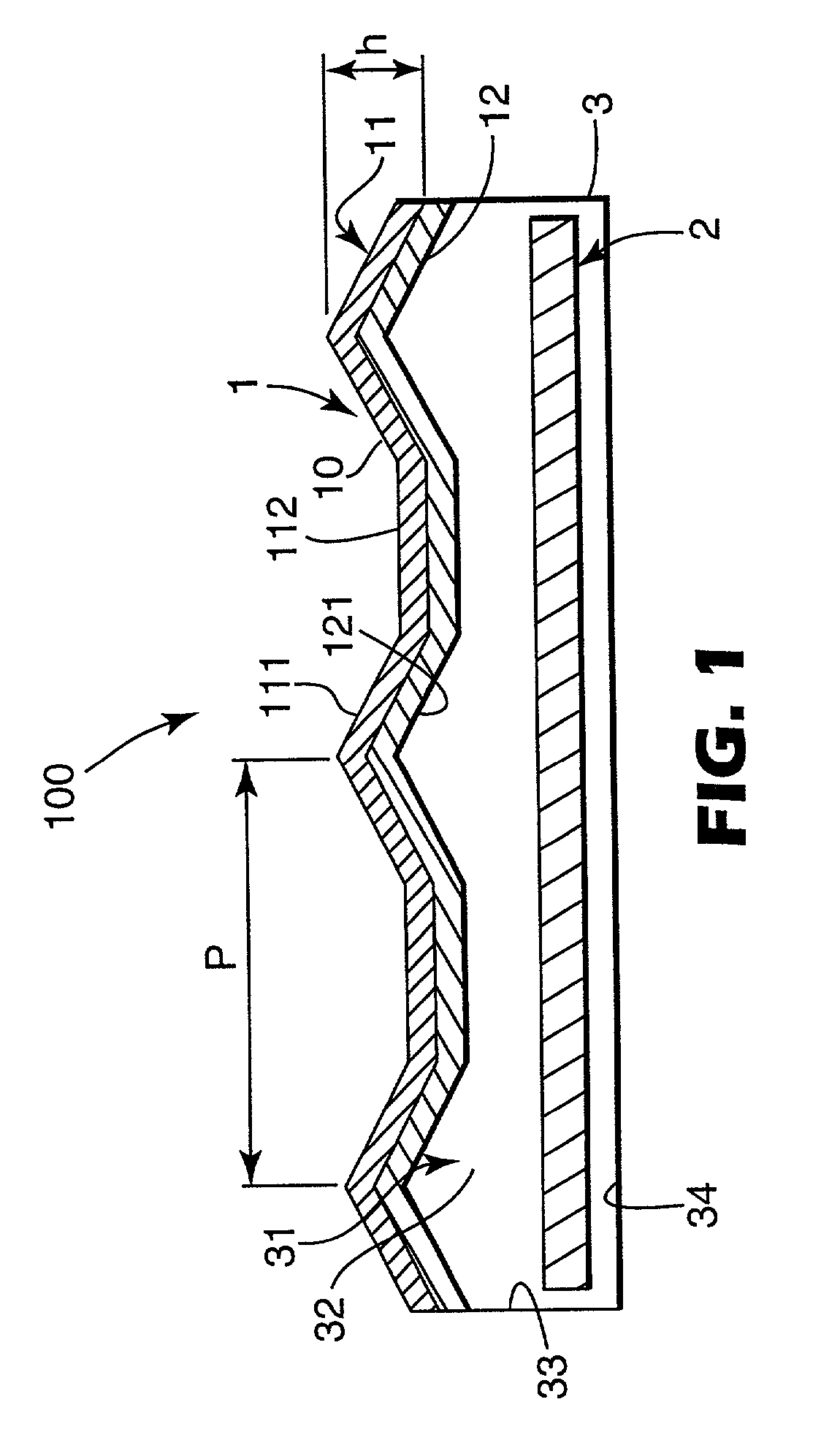
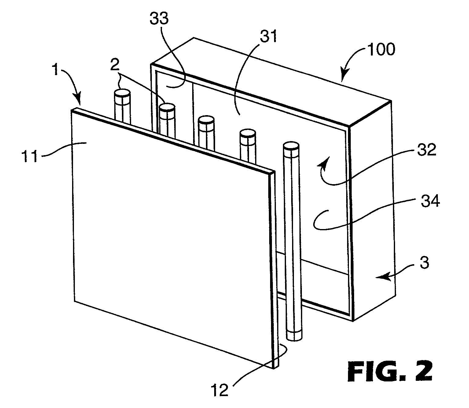
[0119] An expandable plastic sheet was used as a substrate, and a prism-type reflective sheet No. 3963 (manufactured by 3M) was used as a retroreflective sheet. The plastic was an acrylic resin. The sheet had a thickness of 1.0 mm, a tensile strength of 5 kg / mm.sup.2, and a total light transmission of 95%. The retroreflective sheet had a thickness of 400 .mu.m, elongation at break of 10%, a tensile strength at break of 9 kg / 25 mm, and a total light transmission of 15%.

[0120] The retroreflective sheet and the substrate were adhered with an acrylic adhesive which was provided on the backside of the retroreflective sheet to obtain a laminate consisting of the retroreflective sheet and the substrate. The laminate had a total light transmission of 13.7%.

[0121] The obtained laminate was embossed to finish the reflector of the present invention.

[0122] A plurality of projections of an embossing tool were pressed on the backside of the substrate (an opposite surface to the re...

example 2

[0127] A reflector was produced in the same manner as in Example 1 except that an aluminum punching metal was used as a substrate, and the embossing tools were not heated. The substrate had a thickness of 0.3 mm and a tensile strength of 5 kg / mm.sup.2.

[0128] The substrate had through-holes having a diameter of 3 mm, and the pitch of the arranged through-holes was 5 mm. The opening percentage (a percentage of the through-holes based on the whole substrate area) was 56%.


PUM


Abstract

A reflector having a laminate with a light-transmissive substrate and light-transmissive retroreflective sheet is disclosed. The light-transmissive retroreflective sheet is attached to the substrate to cover the surface of the substrate. The reflector has light transmission properties as a whole, characterized in that, a plurality of depressions are formed on the backside of the substrate. A plurality of projections are formed on a reflection surface of the retroreflective sheet.

Description

[0001] The present invention relates to a reflector, a method for the production of a reflector, and an internal-lighting display device. In particular, the present invention relates to a reflector which has light-transmission properties.PRIOR ART[0002] Internal-lighting devices (which may also be referred to as internal light-emitting devices), which use light-transmissive retroreflective sheets as reflectors, are widely used. For example, Japanese Patent No. 2,778,731 discloses an internal-lighting display device comprising a housing (closed container) having a built-in light source, and a reflector which comprises a light-transmissive retroreflective sheet provided on the front surface (light-emitting surface) of the housing. An internal light source, which illuminates the reflector from its backside, is provided in the space of the housing.[0003] The above light-transmissive retroreflective sheet is preferably a so-called prism-type retroreflective sheet comprising a number of c...

Claims


Application Information

Patent Timeline
IPC IPC(8): F21V7/10G09F13/16G02B5/12G09F13/04G09F13/14
CPCF21V7/10G02B5/12G09F13/14
Inventor NAKAYAMA, NAOKIMIZUFUNE, KANYA
Owner 3M INNOVATIVE PROPERTIES CO
Why Eureka
Try Eureka