Lost circulation fluid treatment

a technology of lost circulation and treatment, applied in the direction of filtration separation, separation process, borehole/well accessories, etc., can solve the problem that the fibrous lost circulation material can become trapped between the top two meshes of the screen, and achieve the effect of facilitating loosening and/or washing through of the fiber and further enhancing facilitation

Inactive Publication Date: 2001-10-25
TUBOSCOPE IP
View PDF0 Cites 29 Cited by
  • Summary
  • Abstract
  • Description
  • Claims
  • Application Information

AI Technical Summary

Benefits of technology

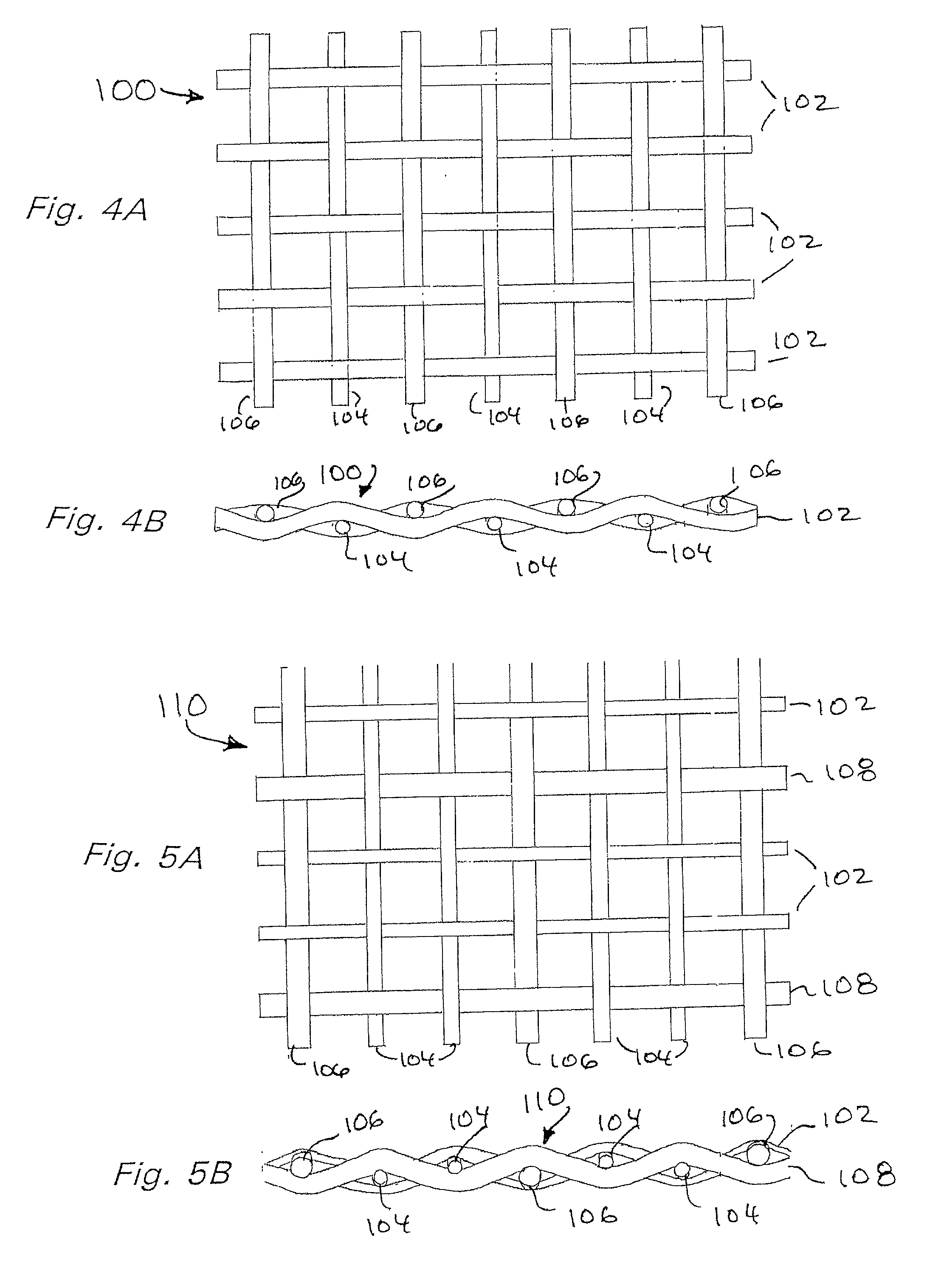
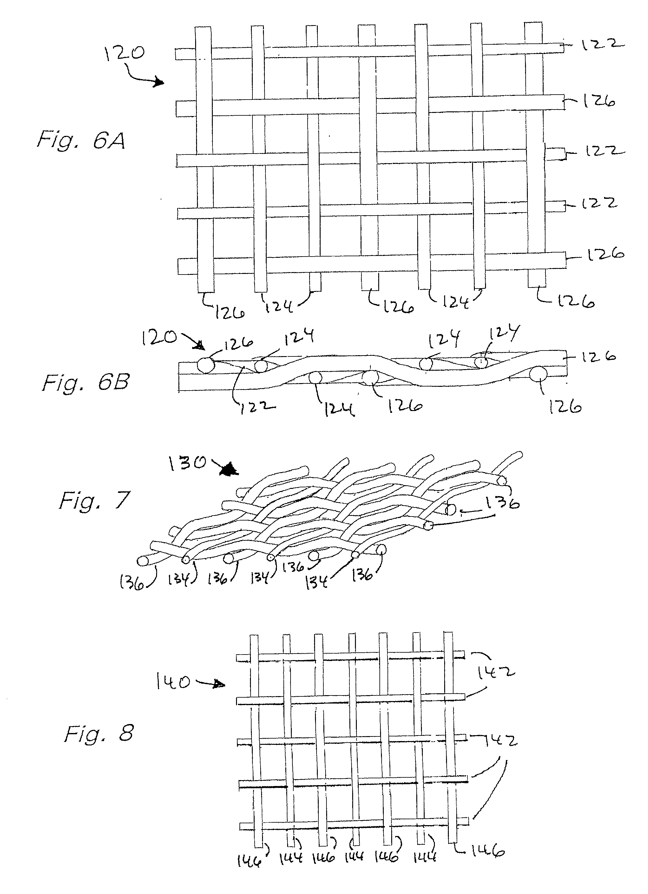
[0024] In certain aspects by using non-square rectangular openings a larger opening area is presented to a fiber than is presented by a square opening with a side equal to the width of the rectangular opening (i.e. the length of the non-square rectangular opening is longer than the length of the side of the square). A fiber caught on a wire and / or bridging such a non-square rectangular opening while connected to one or two wires or laying across two wires of such an opening, does not block flow through the non-square opening to the extent that such a fiber would block flow through the square opening, i.e. the percentage of area of the non-square opening blocked by the fiber is less than the percentage of the total area of the square opening that would be blocked by the fiber. In certain aspects in such a situation there may also be more fluid f low against such a fiber and past the fiber's surfaces when using the non-square openings as compared to the amount of such fluid flow through a square opening. Thus loosening and / or wash through of the fiber may be facilitated by using the non-square openings. Such facilitation may be further enhanced by flowing the fluid to be treated in the general direction of the length of the non-square rectangular openings.

Problems solved by technology

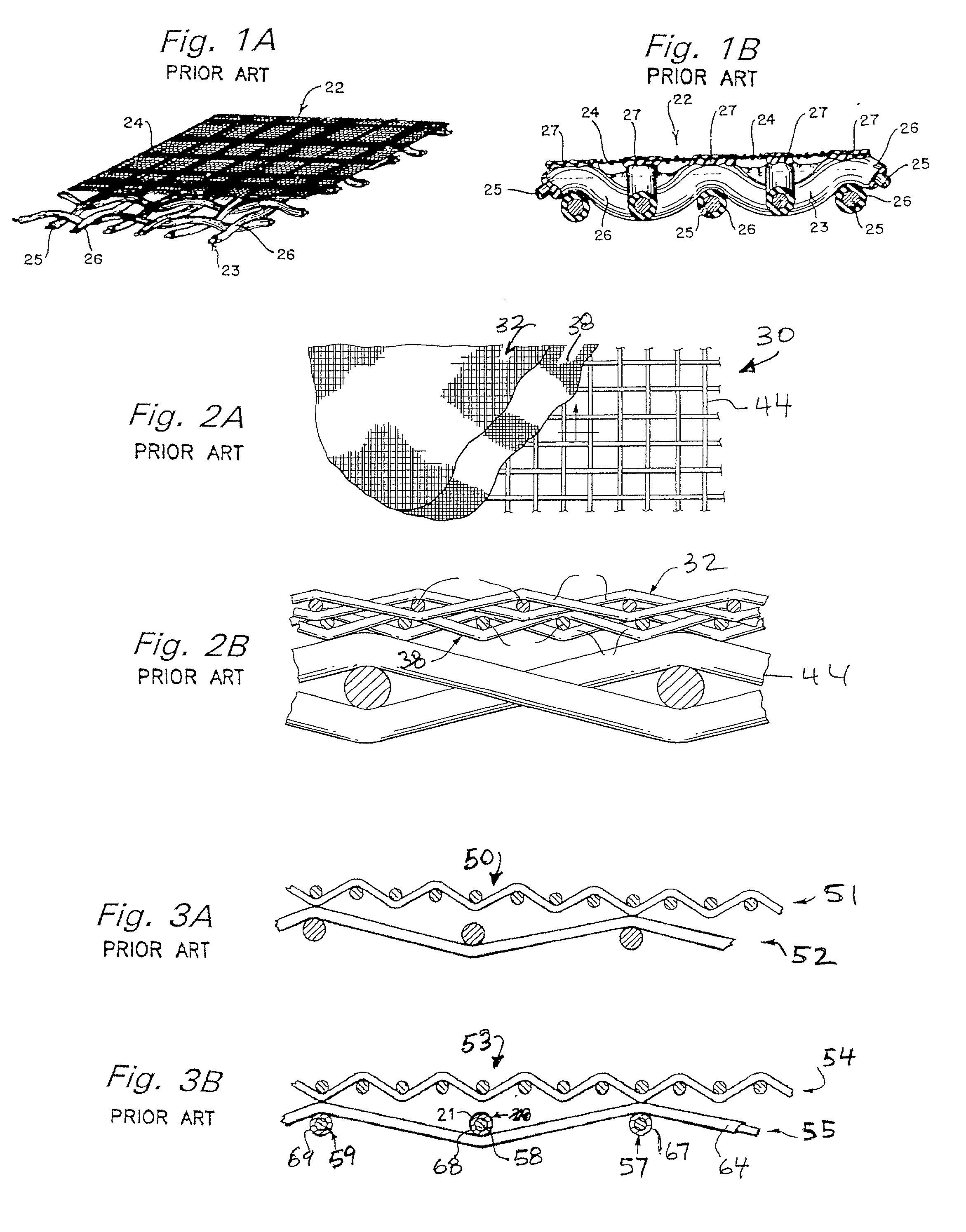
In certain prior art screens that use square mesh openings fibrous lost circulation material can become trapped between the top two meshes of a screen.

Method used


Image

  • Lost circulation fluid treatment
  • Lost circulation fluid treatment
  • Lost circulation fluid treatment

Examples


Embodiment Construction

[0056] FIGS. 19A-19D show a screen assembly 210 according to the present invention which has a lowermost screen 212, a middle screen 214, and a top most screen 216. Any one of these three screens may be deleted. The screen assembly 210 may have any known side hookstrips; and / or any known screen support (indicated by numeral 213) including, but not limited to, support strips, frame, and / or supporting perforated plate (each of which is not the legal equivalent of the others). Any two adjacent or all three screens may be bonded or connected together in any known manner.

[0057] The top screen 216 (see FIG. 19C) is woven of wires about 0.0012 to 0.0018 inches in diameter made of any suitable material, including but not limited to, metal, plastic, steel, and stainless steel, e.g. 304 or 316 ss. Any suitable known weave and weave pattern may be used. In the embodiment of FIG. 19C as viewed from above, the openings between intersecting wires are non-square and rectangular. In the embodiment ...


PUM

PropertyMeasurementUnit
diameteraaaaaaaaaa
diameteraaaaaaaaaa
thicknessaaaaaaaaaa

Abstract

A method for separating fluid from a mixture of fluid and fibrous lost circulation material, the method including introducing the mixture onto a screen assembly that is vibrating for passage of the fluid through the screen assembly and for separation of fibrous lost circulation material from the fluid, the screen assembly comprising a plurality of screens one on top of the other and including at least a first screen and a second screen, one of the screens with comprising a screen mesh woven with non-square openings as viewed from above.

Description

[0001] This is a continuation-in-part of U.S. Ser. No. 09 / 432,959 filed Nov. 8, 1999, incorporated fully herein for all purposes.[0002] 1. Field Of The Invention[0003] This invention is directed to methods for separating drilling fluid from a mixture of such fluid and lost circulation materials and to apparatuses useful in such methods.[0004] 2. Description of Related Art[0005] Often in drilling a wellbore, the circulation of drilling fluid to and then away from the drill bit ceases due to fracturing of the formation through which the wellbore is being drilled. Drilling fluid pumps into the fractured formation rather than being returned to the surface. When circulation is lost because of fracturing of the formation, it is usually supposed that the fracture occurred at some specific depth where the formation is "weak", and that the fracture extends horizontally away from the borehole. Expressions used to describe rocks that are susceptible to lost returns include terms like vugular l...

Claims


Application Information

Patent Timeline
Patent Type & Authority Applications(United States)
IPC IPC(8): B01D29/01B01D33/00B01D33/03B01D39/12B07B1/46
CPCB01D29/012B01D33/0093B01D33/0376B01D39/12B07B1/4663E21B21/065B07B1/469B07B1/4672B01D29/05
Inventor ADAMS, THOMAS C.LARGENT, DAVID W.SCHULTE, DAVID L.
Owner TUBOSCOPE IP
Why Eureka
Try Eureka