Pipe attaching apparatus

a technology for attaching apparatuses and pipes, which is applied in the direction of scaffold accessories, washstands, lightening support devices, etc., can solve the problems of difficult operation, difficult to perform, and use of tools, and exerting relatively substantial for

Inactive Publication Date: 2002-01-03
3 NORTH TECH
View PDF0 Cites 43 Cited by
  • Summary
  • Abstract
  • Description
  • Claims
  • Application Information

AI Technical Summary

Problems solved by technology

One problem with such bolt or screw type clamps is that an installer must manipulate the clamp to insert each of its hook ends into a channel support while lining up the opposite ends of the clamp to receive a bolt.
This process is awkward and time-consuming, and is difficult to perform in locations having poor accessibility.
Although such inventions have as their goal the simplification of the process of installation, all require the use of tools and the exertion of relatively substantial force.

Method used


Image

  • Pipe attaching apparatus
  • Pipe attaching apparatus
  • Pipe attaching apparatus

Examples


Embodiment Construction

[0015] During the course of this description like numbers will be used to identify like elements according to the different views that illustrate the invention.

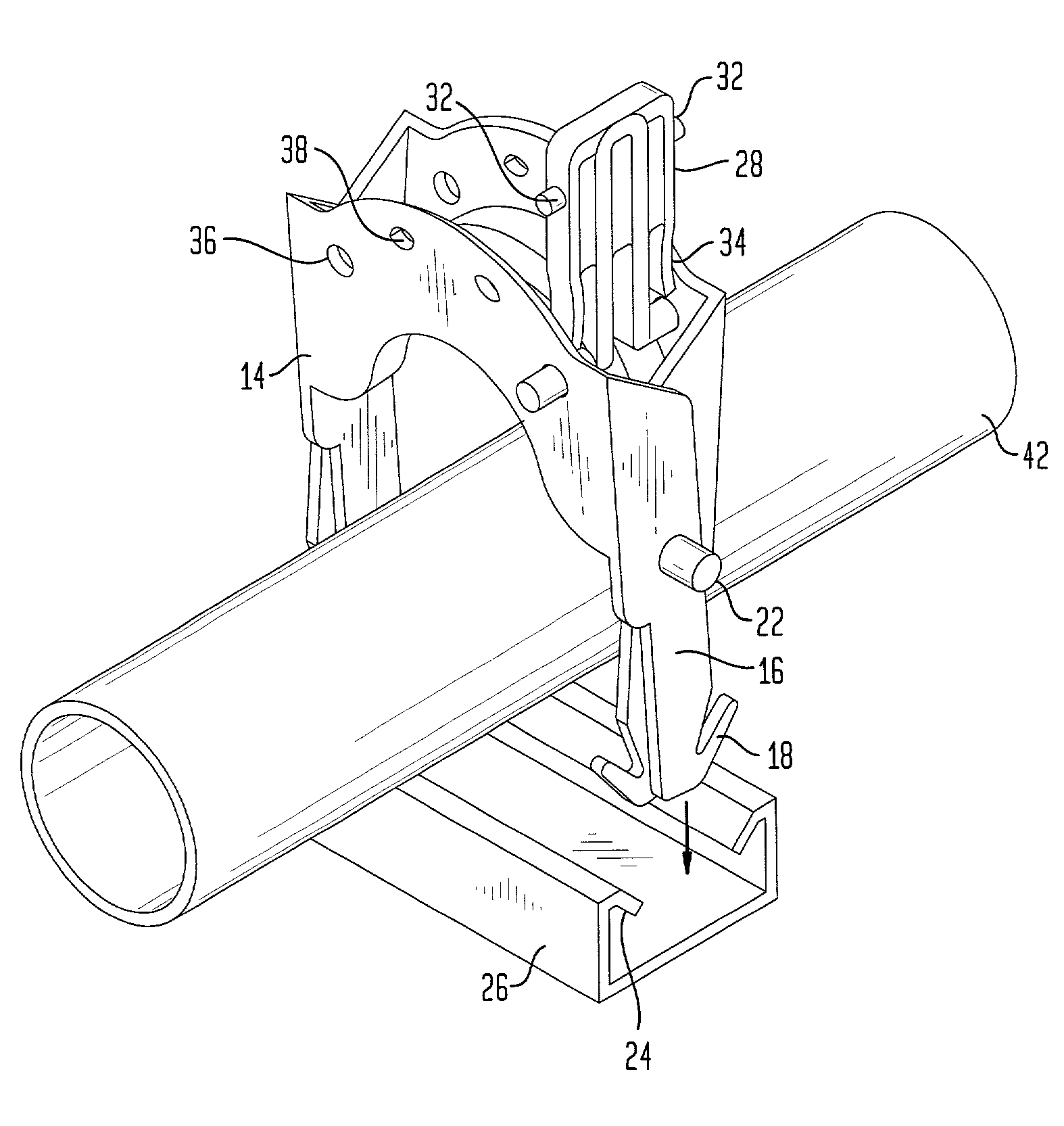
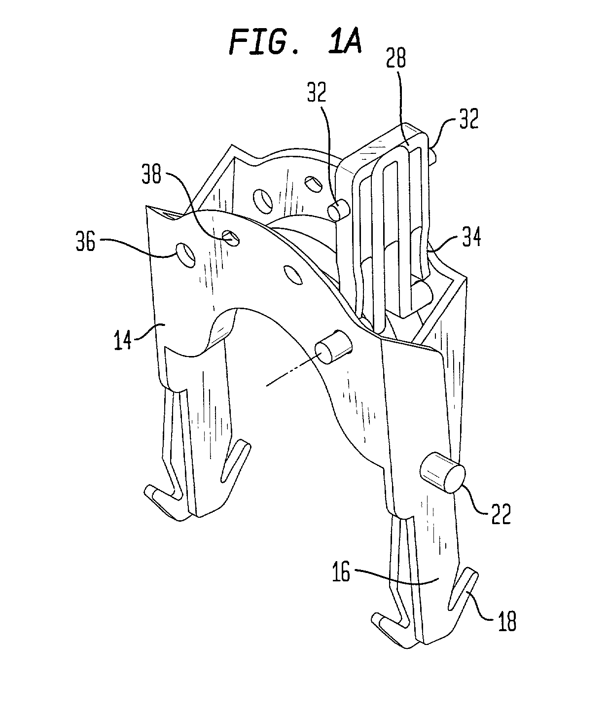
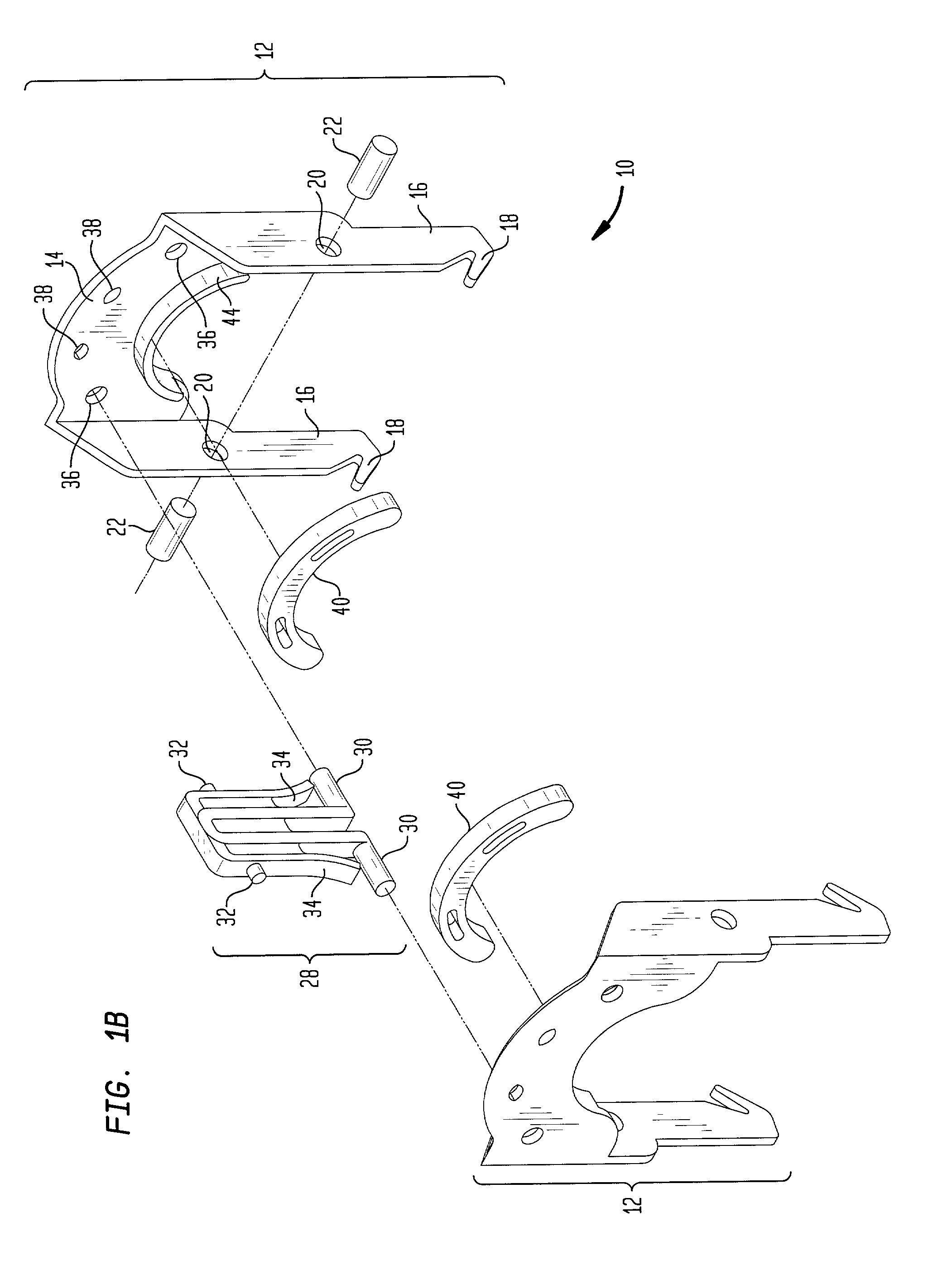
[0016] FIG. 1a illustrates the preferred embodiment of the present invention. FIG. 1b is an exploded view of a pipe attaching apparatus 10 of FIG. 1a. Each of two opposing U-shaped clamp halves 12 has a base plate 14 and two perpendicularly attached side arms 16 as illustrated in FIG. 1b. Each side arm 16 has a hook 18 located at the end of the side arm 16 opposite the base plate 14, and extending away from the base plate 14. Each side arm 16 has a hole 20 proximate midpoint which accommodates a pivot pin 22. Adjacent midpoints of the arms 16 on the oppositely disposed clamp halves 12 are secured by a pair of pins 22 as illustrated in FIG. 1b. Hooks 18 are adapted to engage inturned flanges 24 of a support channel 26 as shown in FIGS. 2a and 2b. Pipe attaching apparatus 10 has a cam 28, which allows for flexing and locking th...


PUM


Abstract

A pipe attaching apparatus is used to attach pipe, electrical conduit and the like to a channel support without the use of tools. With one hand, an installer holds the apparatus containing a pipe between two clamp halves, squeezes a pair of base plates together, inserts a pair of hooks into a support channel and releases the base plates so that the hooks engage inturned flanges in the support channel. Using the same hand, the installer locks the apparatus by engaging a pair of locking pins on a cam in holes in the base plates. The cam in a locked position gives a visual indication of successful installation.

Description

[0001] This application claims the priority of provisional U.S. application Ser. No. 60 / 213,133 filed on Jun. 22, 2000 and entitled "Pipe Attaching Apparatus" by David E. Workman, the entire contents and substance of which are hereby incorporated in total by reference.[0002] 1. Field of the Invention[0003] This invention relates to an apparatus for attaching pipes, electrical conduit and the like.[0004] 2. Description of Related Art[0005] Clamps accepted as standard in the construction industry today for installing pipes and electrical conduit are typically inserted into a support channel and secured by means of a screw or bolt. An example of such a device is marketed by Unistrut Corporation of Wayne, Michigan. One problem with such bolt or screw type clamps is that an installer must manipulate the clamp to insert each of its hook ends into a channel support while lining up the opposite ends of the clamp to receive a bolt. An installer must perform this operation around the pipe, fr...

Claims


Application Information

Patent Timeline
Patent Type & Authority Applications(United States)
IPC IPC(8): F16L3/24
CPCF16L3/24F16L3/243
Inventor WORKMAN, DAVID E.
Owner 3 NORTH TECH
Why Eureka
Try Eureka