Snowblower controls

a technology for snowblowers and controls, applied in the field of snowblowers, can solve the problems of difficulty in ensuring the traction drive and auger engagement of the snowblower, and the operator is unable to exert the necessary force required to turn the machin

Inactive Publication Date: 2002-08-15
DEERE & CO
View PDF0 Cites 13 Cited by
  • Summary
  • Abstract
  • Description
  • Claims
  • Application Information

AI Technical Summary

Problems solved by technology

With handles which extend at the operator, it can be difficult for the operator to exert the necessary forces required to turn the machine.
In other words, as a result of the spacing between the auger and traction levers

Method used


Image

  • Snowblower controls
  • Snowblower controls
  • Snowblower controls

Examples


Embodiment Construction

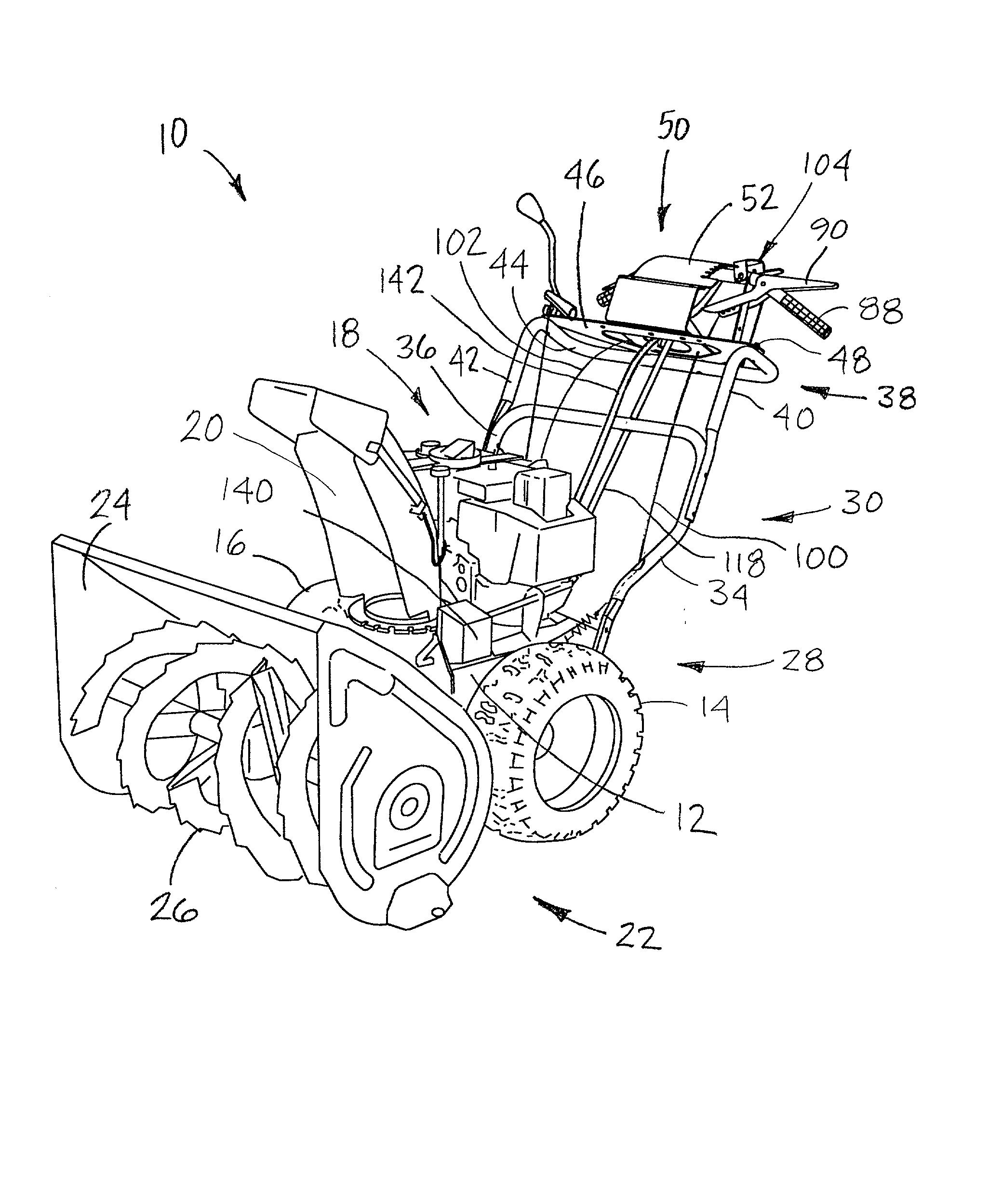
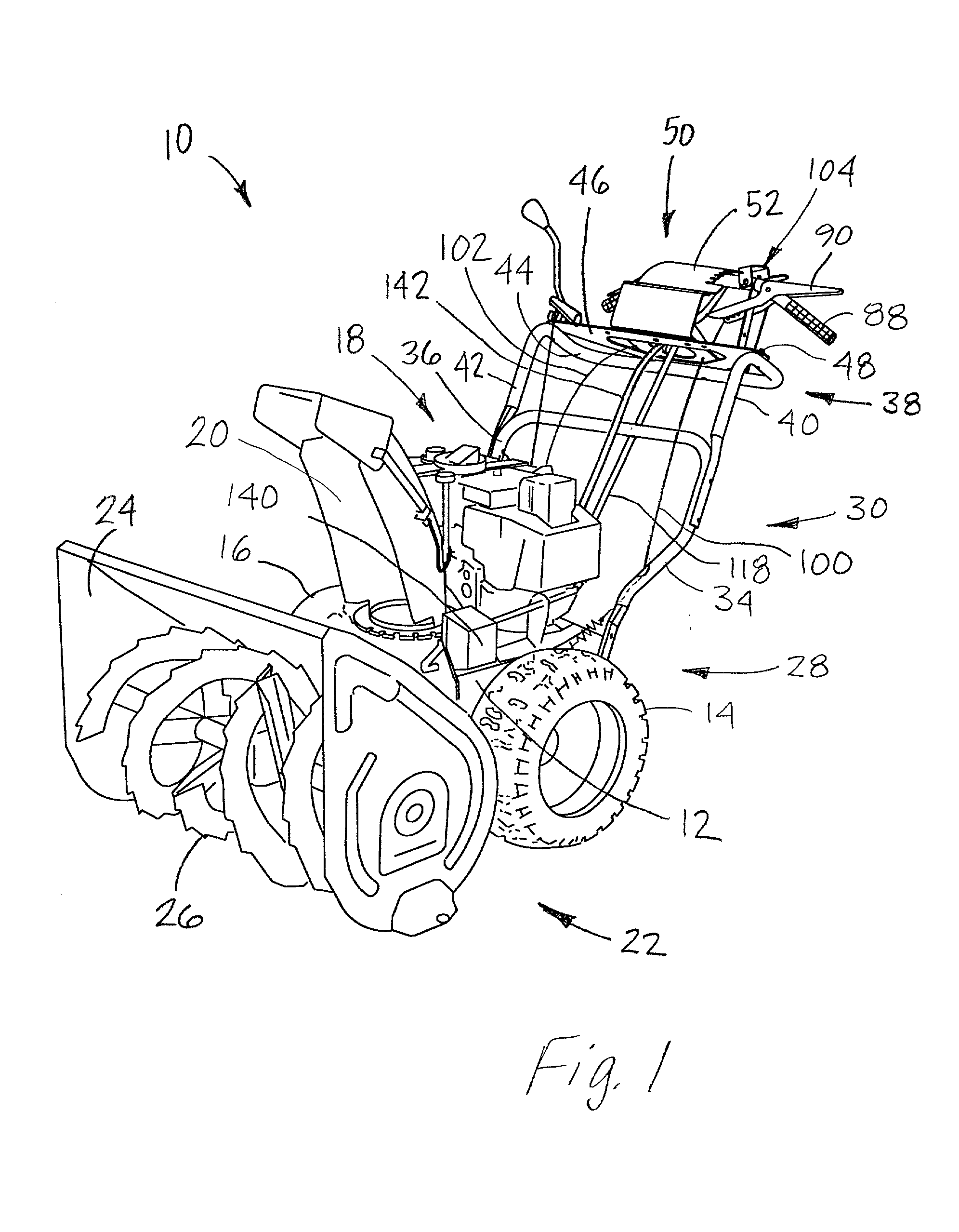
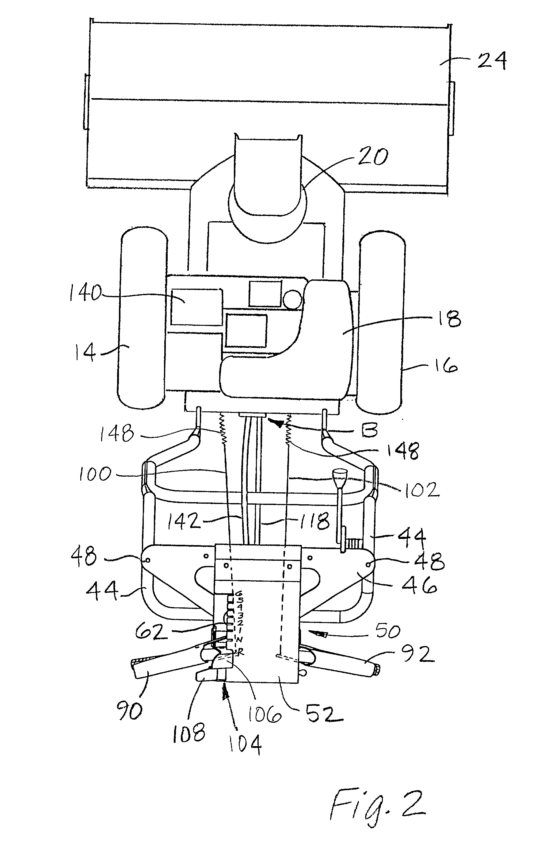
[0022] As illustrated in FIG. 1, there is shown a snowblower 10 having a frame 12 supported upon a pair of ground engaging drive wheels 14, 16 and including an engine 18 and discharge chute 20 mounted with the frame 12. At the front 22 of the snowblower 10, there is provided a collector housing 24 which surrounds an auger 26. The auger 26 is provided as a helical / spiral shape rotary blade which slices through and then shifts snow towards an opening (not shown) in the frame 12. The opening serves as a passageway through which snow is directed to the discharge chute 20. Upon entering the chute 20, snow is directed outwardly and away from the snowblower 10. At the rear 28 of the snowblower 10 is a mounting or handlebar arrangement 30 extending upwardly and away from the frame 12. Arrangement 30 is a U-shaped extension having legs 34, 36 and is connected with the rear portion 28 of the frame 12. Bolted to legs 34, 36 is a further U-shaped handlebar arrangement 38 having a set of members...


PUM


Abstract

A control platform for directing the operation of a snowblower is provided. The platform includes a bail which is pivotably moveable within the platform. Attached to and moveable with the bail are levers for controlling the engagement or disengagement of the drives that power the snowblower's wheels and auger. Also attached with the bail are controls which permit the operator to change the speed and/or direction of the snowblower as well as the orientation of the discharge chute. Through their attachment to the bail and proximity relative to one another, an operator can use each of the levers and controls simultaneously. Accordingly, the platform permits an operator to engage or disengage the drives which power the snowblower's wheels and auger while, simultaneously, enabling a change in speed or direction as well as the direction towards which snow is directed during the removal process.

Description

[0001] 1. Field of the Invention[0002] This invention relates to snowblowers and more specifically to a control structure for engaging the drives to the wheels and the discharge auger and for swingably moving the discharge chute.[0003] 2. Description of Related Art[0004] Snow removal equipment such as walk-behind snowblowers include a frame or chassis to which is mounted a pair of ground engaging drive wheels, an engine, and an auger in the form of a rotary blade for slicing and shifting snow toward a discharge chute where it is then expelled. To assist the operator in directing movement of the snowblower, there ordinarily exists a pair of curved handles which extend upwardly from the chassis. The ends of these handles have grips for the operator to hold and guide the machine as it is operated. Often, the handle and grip portion are bent straight out towards the operator. Typically, both drive wheels are driven together and are not independently powered. Accordingly, snowblowers are...

Claims


Application Information

Patent Timeline
IPC IPC(8): E01H5/04
CPCE01H5/04
Inventor DOWE, JAMES THOMASFRITZ, RODNEY ALLENLOEHR, ROBERT JAMES
Owner DEERE & CO
Why Eureka
Try Eureka