Merchandise display tray with spring-loaded pusher plate

Inactive Publication Date: 2002-10-17
SEARS ROEBUCK
View PDF0 Cites 156 Cited by
  • Summary
  • Abstract
  • Description
  • Claims
  • Application Information

AI Technical Summary

Benefits of technology

0006] The present invention satisfies the aforementioned need by providing a display apparatus that is capable of holding a variety of packaging sizes and c

Problems solved by technology

Consequently, many display systems that are currently employed by retailers are unsatisfactory for adapting to varying packaging sizes used for optical discs, as well as for e

Method used


Image

  • Merchandise display tray with spring-loaded pusher plate
  • Merchandise display tray with spring-loaded pusher plate
  • Merchandise display tray with spring-loaded pusher plate

Examples


Embodiment Construction

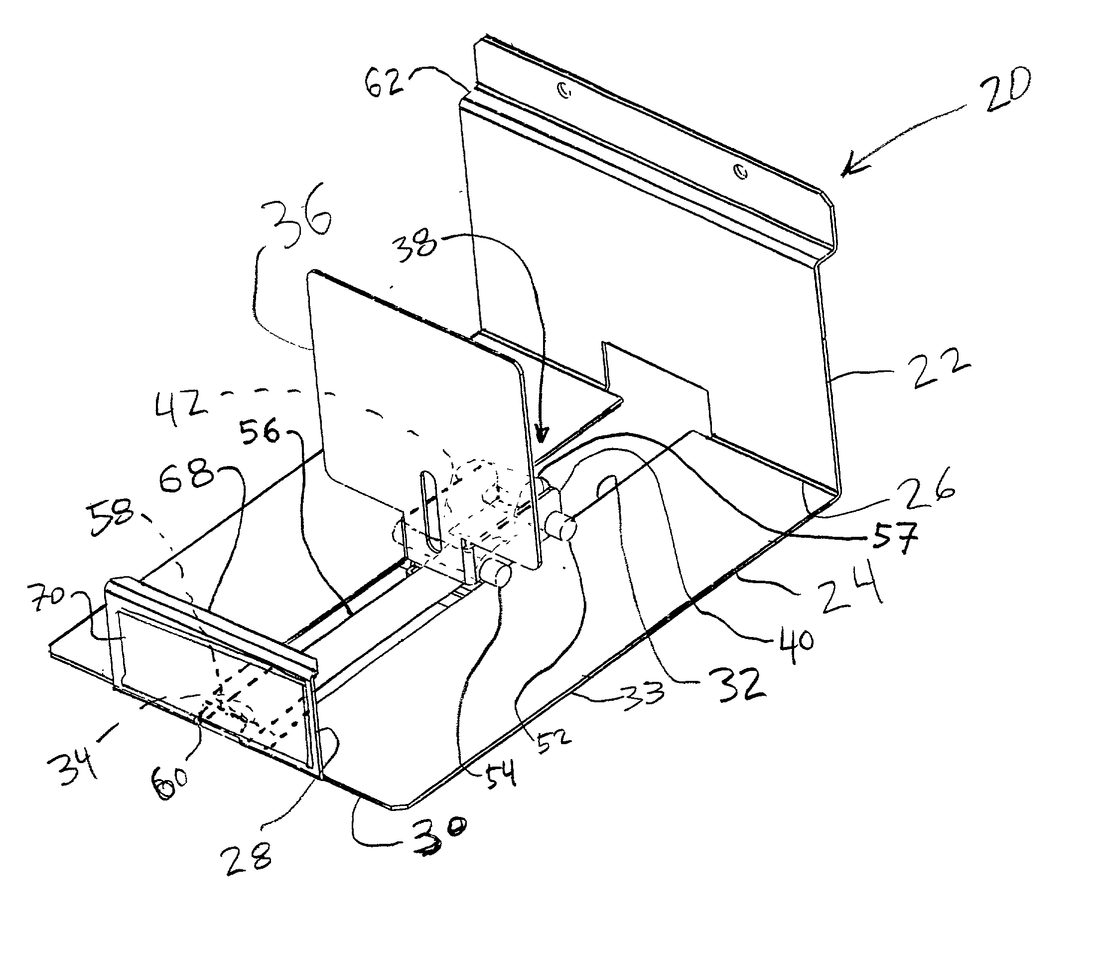
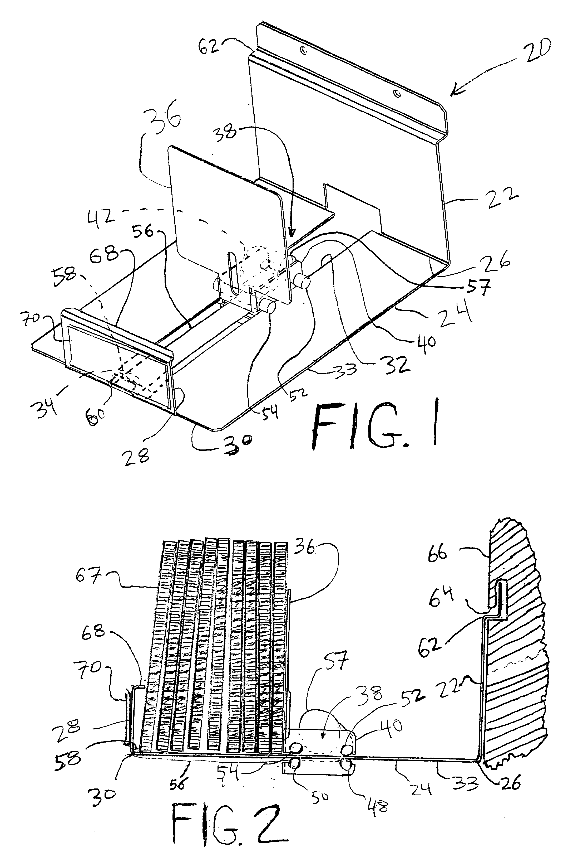
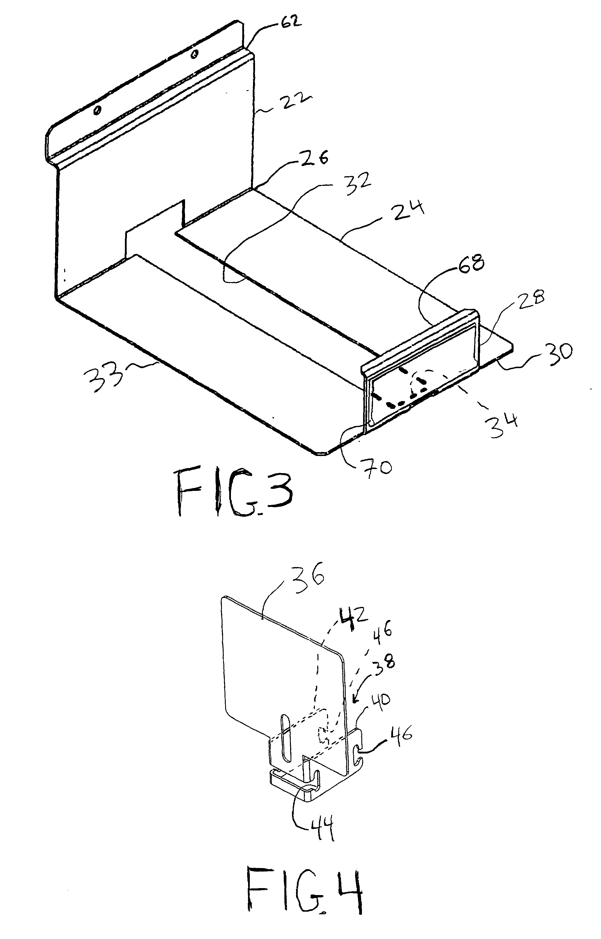
[0018] With reference to FIGS. 1 and 2, a display tray apparatus, generally indicated at 20, includes a generally vertical rear plate portion 22, attached to a generally horizontal base portion 24 at a rearward end 26 of the base portion 24. A generally vertical forward plate portion 28 is attached to a forward end 30 of the base portion 24. The base portion 24 includes an elongated slot 32 that extends from the rearward end 26 of the base portion 24 to a forward slot edge 34 near the forward end 30 of the base portion 24. The rear plate portion 22, the base portion 24, and the forward plate portion 28 together form a fixed tray portion 33, shown in isolation in FIG. 3.

[0019] With reference to FIGS. 1, 2 and 4, a generally vertical pusher plate 36 is slidably mounted to the base portion 24 within the longitudinal slot 32. The pusher plate 36 includes a channel-shaped mounting portion, generally indicated at 38, having a pair of rearward extending flanges 40 and 42, each having a for...


PUM


Abstract

An apparatus for displaying a plurality of merchandise packages is provided. The apparatus comprises a substantially horizontal lower surface, a substantially vertical front plate portion connected to the lower surface, and a substantially vertical rear plate portion connected to the lower surface. The front plate portion has at least one dimension substantially smaller than a corresponding dimension of each merchandise package. A substantially vertical pusher plate is slidably mounted to the lower surface and a resilient member attached to the tray, the resilient member being adapted to urge the pusher surface toward the front plate portion.

Description

[0001] The present invention relates generally to an apparatus for holding and displaying merchandise packages, such as, for example, packages containing compact discs for audio, video discs (e.g., DVD's), software discs, or video game discs (e.g., video game discs for use with Sega Dreamcast.RTM., Nintendo 64.RTM., Sony Playstation.RTM., or Sony Playstation 2.RTM. brand video game systems). More specifically, the present invention relates to a spring-loaded apparatus for holding and displaying merchandise packages.[0002] Optical discs have proven to be an enduring and popular medium for storing large amounts of information for use by consumers, in the audio, video, computer software, and video game industries. Optical discs, although typically uniformly sized at about 4.6875 inches (about 11.91 cm) in diameter, are marketed and packaged using a variety of configurations, such as, for example, plastic "jewel box" cases, in cardboard packaging (such as in simple cardboard sleeves), i...

Claims


Application Information

Patent Timeline
IPC IPC(8): A47F1/12
CPCA47F1/126
Inventor MARIHUGH, DANIEL W.
Owner SEARS ROEBUCK
Why Eureka
Try Eureka