
Optical information recording medium

a technology of optical information and recording medium, which is applied in the direction of data recording, instruments, disposition/mounting of heads, etc., can solve the problems of jitter increase, wcn (wobble c/n ratio) decrease, and push-pull signal of rom (read only memory) area

Inactive Publication Date: 2003-05-15
RICOH KK
View PDF0 Cites 48 Cited by
  • Summary
  • Abstract
  • Description
  • Claims
  • Application Information

AI Technical Summary

Problems solved by technology

Conventionally, there has been a problem in that a tracking error signal (push-pull signal) of a ROM (Read Only Memory) area, which is formed by pre-pits, is smaller than that of a recodable area which is formed by a pre-groove.
Also, as described in Japanese Laid-Open Patent Publication No. 5-36087, there arises a problem that when a pre-pit has wobbling, the WCN (wobble C / N ratio) becomes lower as compared to that with a pre-groove, and jitter increases as the wobbling amount increases.
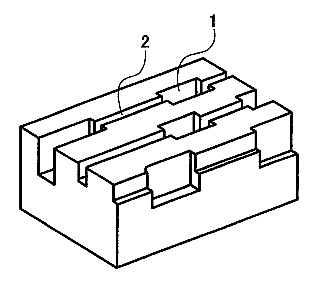
This extension is not uniform, and the angle of inclination becomes small in cross-section of pre-pits 1 in the direction of track, thereby deteriorating the jitter.

Method used


Image

  • Optical information recording medium
  • Optical information recording medium
  • Optical information recording medium

Examples


example 2

(Example 2)

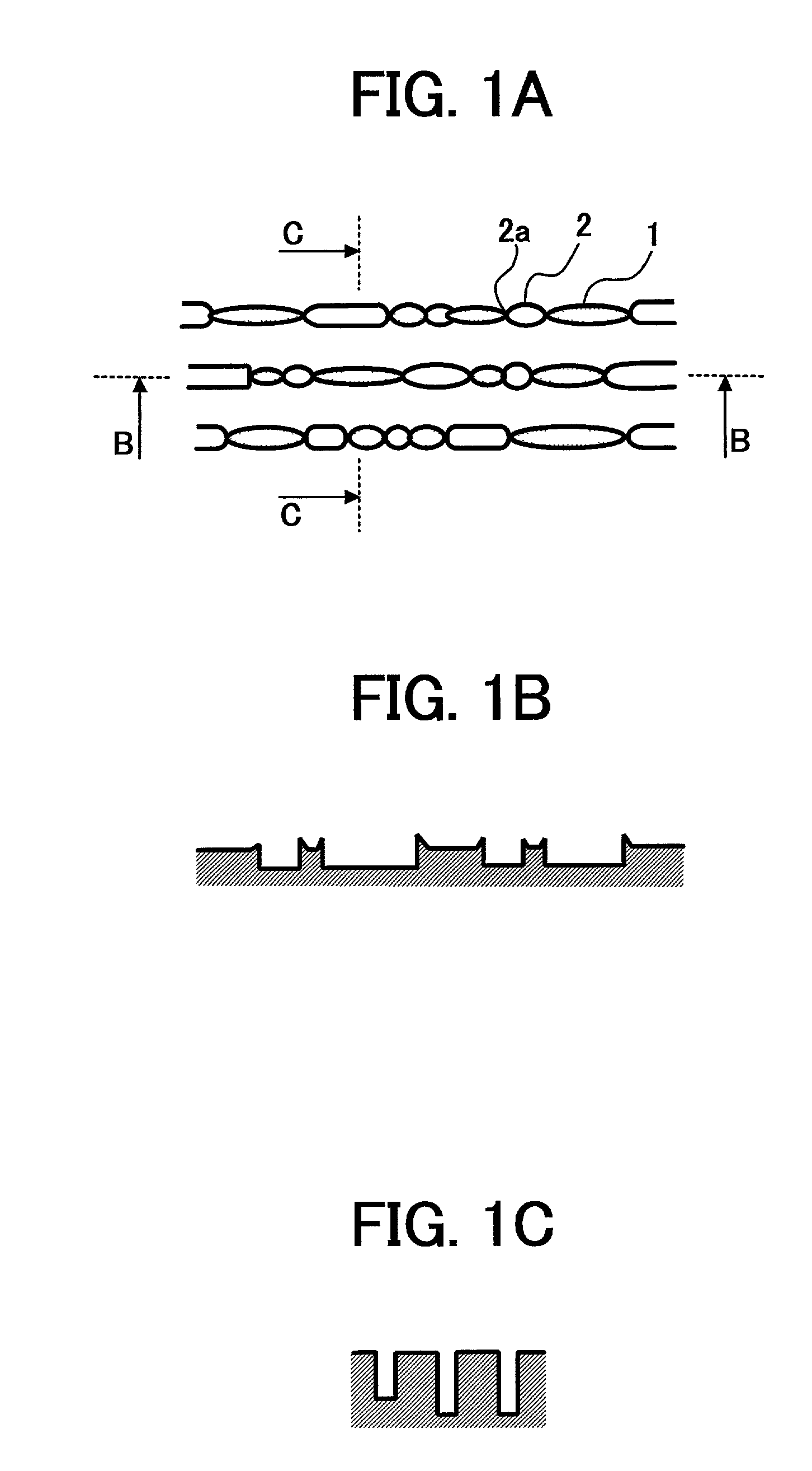
[0063] The present example has the structure as shown in FIG. 1 in the same manner as Example 1, however, the width of the junction part 2a of the groove between pits 2 and pre-pit 1 was smaller than one second of the width of a main part, and the depth of the junction part 2a of the groove 2 between pits and pre-pit 1 was smaller than one second of the depth of a main part, thus the pre-pit 1 and the main part of the groove 2 between pits were separated widely. With the arrangement of the present example, the WCN decreased as shown in Table 1.

example 3

(Example 3)

[0064] The present example has the structure as shown in FIG. 1 in the same manner as Examples 1 and 2, however, the wobbling amount of the pre-pit 1 was kept as it was, and the wobbling amount of the groove between pits was increased to 110 nm. With the arrangement of the present example, the jitter was the same, but the WCN could be increased by 2 dB.

example 4

(Example 4)

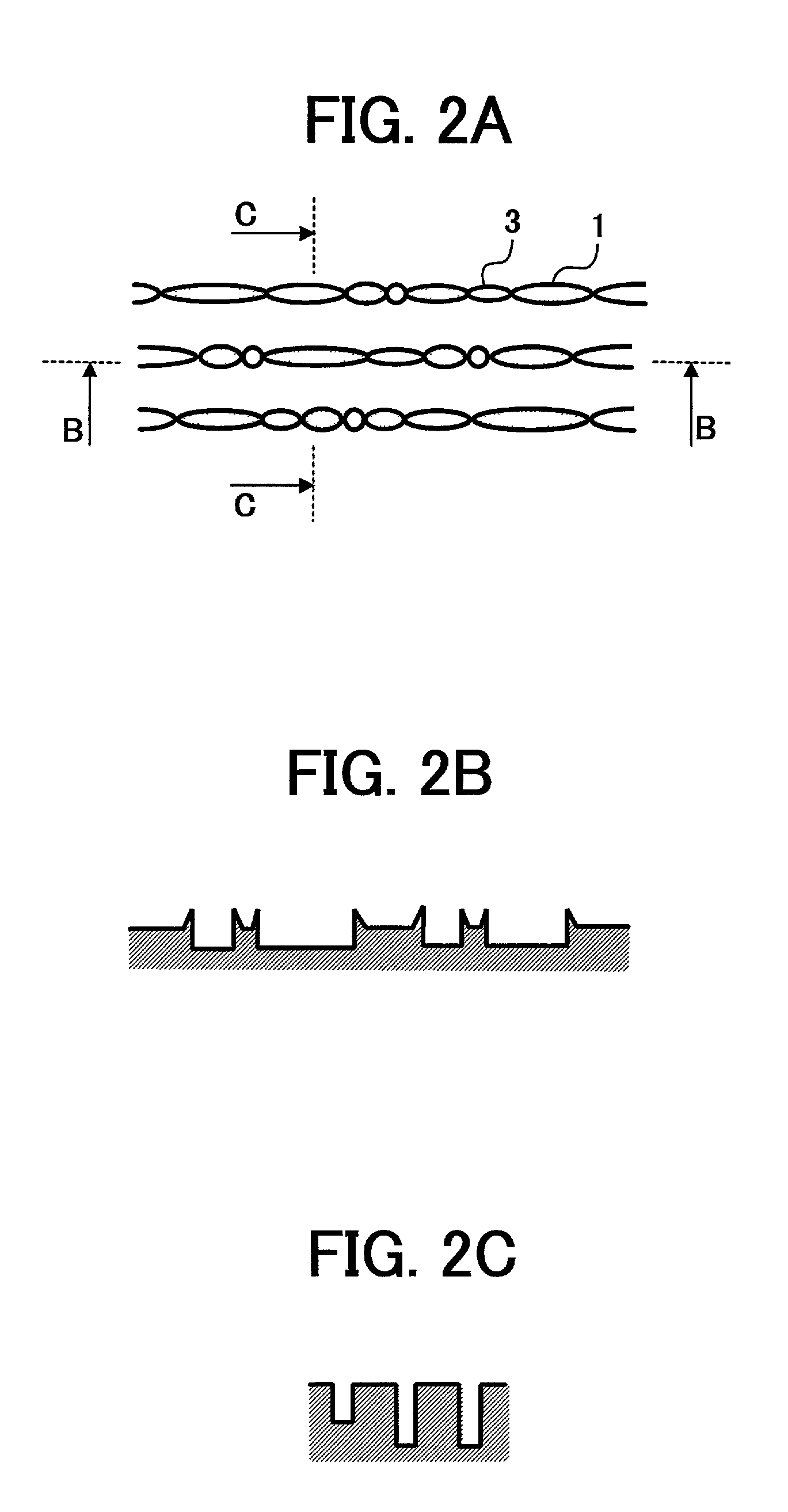
[0065] FIGS. 2A-2C illustrate the structure of an optical information recording medium according to another embodiment of the present invention. FIG. 2A is a partially enlarged plan view illustrating the structure of pits on the surface of a CD-R. FIG. 2B is a cross-sectional view when the CD-R is cut along line B (i.e., in a circumferential direction of the CD-R) as shown in FIG. 2A. FIG. 2C is a cross-sectional view when the CD-R is cut along line C (i.e., in a radial direction of the CD-R) as shown in FIG. 2A. In a ROM area of the present example, a pre-pit 1 having a depth of 3200 .ANG. is arranged, and between one pre-pit 1 and the other pre-pit 1, a pit 3 between pits having a depth of 1800 .ANG. is formed to connect both of the pre-pits together. A substrate which includes the pre-pit structure described above, and a guiding groove having a depth of 1800 .ANG. (not shown in the figure) was created, and also a hybrid CD-R was created. As shown in Table 1, the result...


PUM


Abstract

An optical information recording medium having a ROM area in which pre-pits are arranged in a line in advance, wherein a groove having a depth smaller than a depth of the pre-pits is formed between the pre-pits, and the groove has a width at junction parts smaller than a width of a part of the groove other than the junction parts. Preferably the following relationships are satisfied: ½ Wg<=Wpg<Wg; and Wpg<Wp, where Wp, Wpg and Wg represent a width of the pre-pit, the width of the groove at the junction parts, and the width of the other part of the groove other than the junction parts, respectively.

Description

[0001] 1. Field of the Invention[0002] The present invention relates to an optical information recording medium, more specifically, to an optical information recording medium such as a CD-R (compact disk recordable) medium, and a CD-RW (compact disk rewritable) medium, and particularly, to an optical information recording medium having a ROM area in which pre-pits are arranged in advance and a recordable area in which a guiding groove is arranged.[0003] 2. Discussion of the Background[0004] A recordable compact disk (CD) called "CD-R" is prescribed in the Orange Book, an industry standard. An ordinary CD-R has a pre-groove arranged on its entire surface. The pre-groove wobbles, and by changes of the wobbling period, time information called "ATIP" (absolute time in pre-groove) is recorded. A CD-R is partitioned, from the central part outward, into the following areas: a PCA (power calibration area) in which the light level is set, a PMA (program memory area) in which recording locati...

Claims


Application Information

Patent Timeline
IPC IPC(8): G11B7/007G11B7/013G11B7/09G11B7/24035G11B7/24073G11B7/24079G11B7/24082G11B7/24085G11B7/24091
CPCG11B7/007G11B7/24085G11B7/0938
Inventor SAWADA, YASUOFUJIWARA, YASUHIDE
Owner RICOH KK
Learn More